 |
||||||||||||
| Home |
|
Products For Sale |
FAQs, Tips, Manuals |
Referral List |
|
Photo Gallery |
|
Links |
|
Contact Us |
|
|
||||||||||||||||||
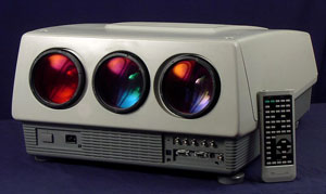
DEFLECTION BOARD
Great! Well, let's lift the Deflection board. The Deflection board is the
board with the large heatsink
attached to it. You will find 2 screws or 4 screws on the back edge of the board
that have to be
loosened. The 2 lower screws in the picture above are held by plastic washers
and DO NOT come
out. There MAY be a metal shield that has to be removed. It is often already
missing. The
Deflection board should now hinge up. Below the deflection board you will see
the red and green
CRTs, as well as the CONVERGENCE (C-Drive) and FOCUS (F-Drive) boards. If you
need to
At this point the projector should be configured as outlined on the cover for
the mounting method
desired. Now look at the tubes. The front is a bell shaped glass envelope
tapering down to a thin
tube called the neck. The first item right up against the .bell. is the
deflection yoke. Look for 2
small rings with tabs on them (A). Those are the CENTERING magnets. Moving these
around the
tube, and in opposition to each other allows you to position the raster in the
center of each tube.
Now is a good time to carefully cut the silicone dab that should be on the
rings. Do this on all 3
tubes. Moving down the tube, you will see a long thumbscrew (B). This is the
clamp that holds the Proper adjustment of the astigmatism magnets is crucial to achieve tight
focus across the screen,
and will be explained further on. You might want to carefully cut the silicone
on these rings as well.
NOTE: If this is beginning to sound too difficult, I highly recommend hiring a
professional for the
job at this point. This is an advanced, but important procedure to achieve good
results with a PG.
It is also dangerous to the novice, since the following adjustments are made
with power applied to
the projector. I cannot stress enough that this is dangerous for the
inexperienced.
|
|
|||||||||||||||||
 NEC PG Series


© Copyright CurtPalme.com. All Rights Reserved. |