 |
||||||||||||
| Home |
|
Products For Sale |
FAQs, Tips, Manuals |
Referral List |
|
Photo Gallery |
|
Links |
|
Contact Us |
|
|
|||||||||||||||||
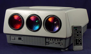
Around the set
Here’s a top view of a typical NEC PG set. The system, wave, control and point convergence boards are located under the metal shield cover. A sticker on the top of the shield identifies each of the board locations. Note that it is possible to install the boards in the wrong order. The set will stop working if you do that. Also note not to remove or install the boards when the power cord is plugged in.. Power is supplied to these boards all the time, and it’s possible to blow them when the set is in standby mode. Unplug the power cord for a good 5 minutes before disturbing these boards. The large board covering the green and red tubes is the deflection board. This board has the H and V output and circuitry on it as well as some keystone and pincushion circuits. The H and V yoke connectors are also located on this board. The deflection board aluminum frame flips up to expose the red and green tubes. The HV board is located in the rear right corner of the set. Below is a closer look at the shield that covers the video board. The HV board sits vertically in the set, and fails rarely. The HV splitter is on the left side of the set, and the feed form the HV transformer and the three HV leads from the three tubes plug into this splitter as well.
The back cover of the set houses the manual switches that control some functions of the set. If your remote dies, at least you can turn the set on and off right from the projector. You cannot control the various convergence or other menu functions from these controls, you do need the full remote to fully access the set. There is a dual segment LED display that will read ‘00’ if the set is working properly. The display will (usually) display an error code if there’s a fault in the set, and (usually) the error code will direct you to the right area of the set that’s faulty. Note that this display is not 100% accurate, and some faulty error codes have been known to be displayed when something fails. There is a small hidden fan behind the right rear cover on some sets. This serves to cool the HV board. This fan can shatter while the set is in transit, and a ‘fan has stopped’ error code will appear on the screen. Don’t overlook this fan if you get this error message on the screen. Also note that these fans are a three wire model. The yellow wire senses if
the fan is spinning or not, and the set will shut down if a fan stop is
detected. You cannot swap out these fans with two wire models without
modifications to the fan sensing circuit. Flipping up the deflection board exposes the red and green tubes (note that NEC has switched the location of the R and B tubes over most other manufacturers). The below image shows the locations of the convergence (C) and focus (F) boards. These boards are amongst the most common failures of the NEC PG series, fortunately they are usually easy to repair.
Both the F and C boards are held to the bottom of the chassis with three small Philips screws. You need a long Philips screwdriver (preferably magnetized) to remove these screws. No magnetic screwdriver? When reinstalling the board, wrap the screwdriver and screw in 1 layer of masking tape, and you won’t lose the screw when it’s deep in the set. All of the edge connectors on the F and C boards unplug for easy servicing of these boards. There is a layer of rubber type insulation which acts as a heat conductor between the small aluminum heatsink of the F and C boards and the chassis. Some people remove this insulation and replace it with liberal amounts of heat sink compound to improve the heat transfer. I can’t comment whether this improves the heat flow. The above image also shows the CRITICAL color balance pots that are attached
to one of the video output boards. DO NOT under any circumstances touch these
pots, as tempting as it may seem. Even as a seasoned tech, setting the proper
color balance is one of the trickiest things do. Don’t mess with them!
|
|
||||||||||||||||
 NEC PG Series


© Copyright CurtPalme.com. All Rights Reserved. |