 |
||||||||||||
| Home |
|
Products For Sale |
FAQs, Tips, Manuals |
Referral List |
|
Photo Gallery |
|
Links |
|
Contact Us |
|
|
||||||||||||||||||
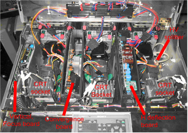
Rear of the set: Once the top cover is lifted up on the back of the set, the CRT area is exposed, and the G70 doesn’t differ much from other CRT projectors with it’s layout. The HV splitter is located to the right of the blue tube, and the HV leads are snaked under the front of the tubes. The CRT sockets also contain the video output amplifiers, and therefore have the large heatsinks on them. The vertical/focus, convergence and H output boards are housed in plastic sleeves, and each board pulls up and out of the plastic sleeve.
The back of the set is covered by two metal shields that cover the rest of
the boards found in the G70.
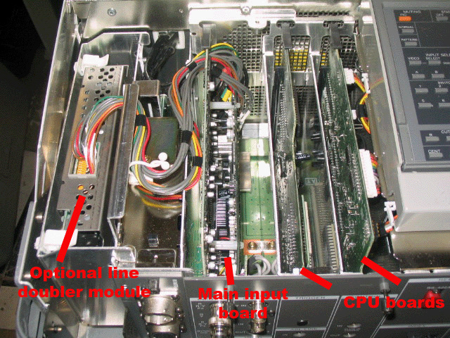
To the far left is the optional line doubler module that plugs into the main RGB/Video input board, also called the B board. If you pull out the B board, note that there are 6 shielded cables plugged into the back of the board. These connectors are relatively fragile, and it’s easy to rip out the wire from the connector. Unplug the connectors from the board via the metal part of the connector, do not pull on the cable, and remember the right order that the 6 cables connect in, it’s important! Next to the video input board are the two CPU boards, called the Ya and Yb boards. These two boards work in conjunction with one another. There are several versions of software on these boards, and the software versions of the Ya and Yb boards must be compatible to work with each other, otherwise you will most likely see an ‘88’; error code on the set, and the projector will not power up. There are several switches on this board, including the master reset switch. My VERY STRONG recommendation is NOT to engage these switches, as I have had permanent failure of these boards when a hard reset is done in the field. If you want to reset the values of the convergence to the default ‘128’, I’d suggest you do it manually by going through each convergence setting. That takes a lot longer, but you’ll have a working set when you’re done. PA board: This board controls the high voltage section and also has an auxiliary power supply that feeds various sections of the set. There are high voltage adjustments on this board. DO NOT adjust those, for risk of shattering your tubes. Under normal use, these pots never need adjusting.
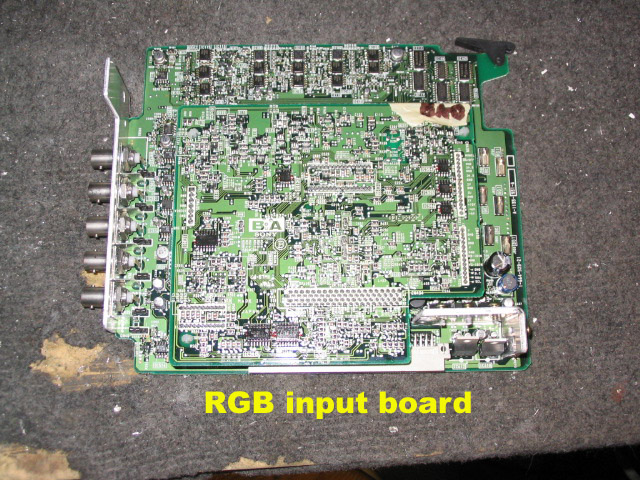
RGB input board: This board contains all of the video processing, so that a video, component or RGB signal is processed, and the output is fed right to the CRT sockets and tubes. Be careful when pulling out the mini RCA connectors, as the wires can pull out of the metal connectors. Pull out the wires via the metal connectors only!
|
|
|||||||||||||||||
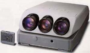 Sony G70

© Copyright CurtPalme.com. All Rights Reserved. |