 |
||||||||||||
| Home |
|
Products For Sale |
FAQs, Tips, Manuals |
Referral List |
|
Photo Gallery |
|
Links |
|
Contact Us |
|
|
|||||||||||||||||
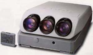
Here is an overview of the modules and components of the Sony G70 projector. Unlike a bunch of other sets on the site here, there are literally no internal adjustments that are required on this model, so people that like playing with controls that they shouldn’t be will be somewhat disappointed in this set. Let me be perfectly clear: Any trimpots found on the boards in this projector SHOULD NOT BE TOUCHED. I have yet to see a projector that needs tweaking of the internal controls, all installation and alignment adjustments are done via the projector menus and the controls on the keypad or the remote. Under the top cover: The top cover is relatively easy to remove: Undo the two screws over the lens cover, lift the lens cover up, rotate the two large flat head screws 90 degrees, and the whole top cover will lift up and off of the set. (the two large flat head screws do not remove from the case). Removing the lens cover off the front of the set is easy once you find the release tabs of the cover shown here (behind my finger):
Pull the two metal tabs towards the outside of the case, and the front cover will hinge forward and come off the set, exposing the lenses. Under the top cover are the yoke connectors and switch that allow you to flip the orientation of the image. The three blue/red wire connectors flip the image horizontally, the small switch flips all three images in the vertical direction. There are two positions for the H yoke connectors, the connectors must be flipped and inserted into the other jack to flip the image:
|
|
||||||||||||||||
 Sony G70


© Copyright CurtPalme.com. All Rights Reserved. |