CPC Magnet Adjustment of Beam Astigmation Note: This adjustment
procedure is similar in concept to the one outline here.
It is still included in this article for sake of completeness.
Warning: This adjustment is for advanced setup technicians only. Novices
and non-technicians are warned to avoid performing astigmation CPC magnet
adjustments. Adjustment of CPC magnets should ONLY done by advanced setup
personnel. Improper technique will render focus impossible. High voltage shock
and tube neck fragility are also significant hazards during CPC magnet
adjustment.
Electron beam focusing lenses are not perfectly uniform. Also, the direction
of the earth's magnetic field can cause the beam to enter the lens off center.
Astigmation of the beam fine tunes the lens uniformity and centers the beam as
it enters the lens. This allows the beam lens to create a small electron spot
with minimal flaring. Poor astigmation can make good electron beam focus
impossible.
Static electron beam astigmation is carried out using CPC magnets (called
Color Purity Control for historical reasons) on the tube neck and/or electronic
astigmation controls. If both CPC magnets and electronic "dynamic" astigmation
controls are present, it is best to let the CPC magnets do most of the work and
have the electronic astigmation system merely fine tune the effects. One must
neutralize the electronic astigmation controls prior to adjusting CPC magnets.
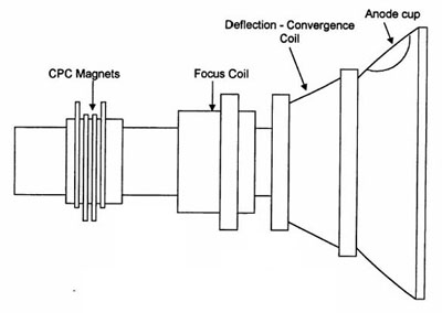
CPC magnets are arranged as pairs of rings about the end of tube neck near
the socketed drive board. They should not be confused by the much more forward
raster centering magnets just behind the deflection yoke. Projectors don't
always have the full set of 2, 4, and 6 pole CPC magnets. CPC magnet assemblies
vary in appearance and mechanical design. Sometimes the ring pairs have a small
knob allowing one to adjust the angle between the two rings of a pair. More
often one merely sees tabs with which to manipulate the rings. The CPC have 2,
4, or 6 magnetic poles, but don't confuse that with the number tabs on the
rings. One cannot actually see the poles. By varying the angle between the two
rings of a pair (moving tabs in opposite directions or twisting a little knob)
one varies the intensity of the effect. Rotating a pair about the axis of the
tube neck (moving tabs in same direction or twisting little knob in opposite
direction) changes the directionality of the effect. If all three sets of CPC
magnets are present, the rearmost is the 2 pole (centering). The middle is the 4
pole (ovalness). And the most anterior (if present) is either non-functional or
a 6 pole correction (triangularity).
I'll reiterate since this seems to confuse some people....
Intensity: The amount of effect that a magnet ring pair creates. For instance
if you consider the two pole magnet pair, you can make the rings cancel each
other out or augment each other by varying the rotation of the two rings
relative to each other.
Directionality: The orientation of the net magnetic effect. If you spin a
ring pair TOGETHER around the tube neck you spin the direction in which the
poles affect the electron beam. Notice that this minimally changes how the poles
cancel or reinforce each other. Spinning the pair together merely lets you vary
the direction in which that magnet ring pair squeezes or expands the beam.
Spinning a pair together changes the direction of the effect, but making the
two rings of a pair spin in opposite directions changes the amount of their
effect.
Because the factory performs CPC magnet alignment, shipping can shift
controls, and end users are not expected to make these adjustments, the CPC
magnets are usually held in place with some silicone adhesive. This must be
removed carefully. Very cautious picking at the adhesive with fingers will
usually free the controls. Do not mechanically stress the tube necks!
Again, neutralize all electronic astigmation controls prior to working with
CPC magnets. On projectors which lack separate electronic astigmation controls,
perform CPC and electronic astigmation while the highest scan frequency to be
used is displayed.
I assume you know how to change the electron beam focus and don't get that
confused with optical focusing.
The 4 Pole (middle) CPC magnets affects ovalness of the electron beam lens.
Adjust this while displaying a dot pattern with contrast set moderately high.
Intentionally UNDER focus the electron beam making the dots into uniform blobs.
Adjust the 4 pole magnets to make the center blob as perfectly circular as
possible. Physically walk up to the screen to judge shape. Turning the small
knob or moving adjustment tabs in opposite directions alters the amount of
ovalness. Spinning the 4 pole rings around the axis of the tube neck changes the
direction of the ovalness axis.
The 2 Pole (rear) CPC magnets centers the electron beam in the electron beam
lens. Adjust this while displaying a dot pattern while contrast is moderately
high. Intentionally OVER focus the electron beam making the dots into a flare
with a bright central core. Turning the small knob or moving adjustment tabs in
opposite directions alters the amount of deflection. Spinning the 2 pole rings
around the axis of the tube neck changes the direction of deflection. Make the
bright core centered in the flare.
Go back and forth between the 2 and 4 pole adjustments to get things right.
As a final check, carefully watch the dots as you go from under to over focused.
The dots should stay almost motionless as you vary the beam focus. If they move,
redo the 2 pole adjustment.
You will have to redo raster centering after adjusting the CPC magnets. If
working on the blue gun, you'll probably want to leave the electron gun
underfocused enough to make its light output measure about 20% higher than its
fully focused state to improve grayscale tracking at higher light output.
Guy Kuo
Director - Imaging Science Foundation Research Lab
| Did you find this information useful? Please consider making a
donation to help defray the cost of managing and hosting future
articles, tips, and documents. |
|
|
|
Or
purchase
from
Amazon.com
and a small percentage automatically
goes to support this site at no extra cost to you! Visit their
Blu-ray and
4K UHD
stores for sales.
Want to show off your
home theater? See our
Blu-ray Release List & Must-Have Titles. |
|

|
|

|
