 |
||||||||||||
| Home |
|
Products For Sale |
FAQs, Tips, Manuals |
Referral List |
|
Photo Gallery |
|
Links |
|
Contact Us |
|
|
||||||||||||||||||
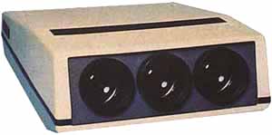
RGB Board:
The above picture is the analog RGB input board for the Ampro projectors. Again, there are several versions of this board, not all of which are compatible with others. The only adjustments on this board are the 5 pots as labelled above. The Ampro manual does a good job telling how to set these pots up. Too much pressure on the pots, and they will shear off. Not labelled on the above picture are the 3-2 pin video output connectors on the back of the board that feed the video signals to each CRT socket. Note that these connectors are direction specific. If you install the connectors backwards, you’ll get no video image on that particular tube. Also not labelled above are the three small RGB level trimpots on at each BNC connector. The default setting on these multi turn trimpots is fully clockwise. These are 10 turn pots, and they will audibly click when the max CW point is reached. I've received many surplus units in with these controls turned way down, and the result is a weak color when an RGB signal is being used. These controls can be used to gain balance all three colors when an RGB signal is used. Note that the stock RGB card uses an RGB signal with a combined H and V sync
connector labelled ‘s’ for the sync. If your RGB source has separate H and V
cables, then use a BNC ‘T’ connector to combine the two leads into one.
|
|
|||||||||||||||||
 Ampro 1500/2000

© Copyright CurtPalme.com. All Rights Reserved. |