 |
||||||||||||
| Home |
|
Products For Sale |
FAQs, Tips, Manuals |
Referral List |
|
Photo Gallery |
|
Links |
|
Contact Us |
|
|
||||||||||||||||||
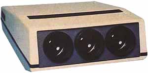
CRT Socket:
Pictured above is weak point # 1 in most Ampro projectors. The CRT socket/video output board is susceptible to failure due to the occasional HV arc within the tube (completely normal, but the Ampro CRT socket is not overly well protected for internal tube arcing). Fortunately I stock a lot of CRT sockets. The common complaint is that the particular tube color comes on at full brightness, and a ‘high beam current’ fault will show on the remote before the set shuts down. The trick to finding which CRT card is at fault is to pull the CRT card off the tube socket, and then power the set back up. The remaining two tubes will work normally when the bad CRT socket is disconnected from the tube. Note that on rare occasion a picture tube will short out, damaging the socket and causing a high beam current error.. In that case, the tube and socket need to be replaced. The wiring is fairly self explanatory above. The G2 connector has about 800 volts on it, and provides the master brightness to each tube. The method to properly set the G2 is simple. Use the tube cutoff switch on the remote, and mute all three tubes while the set is on. Use the G2 control to set the raster of each tube to just barely be lit as looking directly into the tube. Then turn the CRT’s back on. All G2 levels are now properly set. Note that the CRT sockets used two types of G2 leads. The one pictured is the older style that plugs into the motherboard. The later boards used a mid air connector. The connectors may be changed over, the two styles of boards are otherwise identical. Note that the 2 pin video connector is polarity sensitive. If the video wire is connected backwards, a very dim or no video image will be seen on that tube. Pull the video connector off and reinsert in the opposite direction. The focus lead connects to the appropriate focus lead coming from the HV
block or HV power supply. These connectors can get leaky over time, and cause
intermittent focus if they arc or leak to the chassis. This is a rare occurrence
however.
|
|
|||||||||||||||||
 Ampro 1500/2000

© Copyright CurtPalme.com. All Rights Reserved. |