 Barco 808/Cine8 Barco 808/Cine8
Layout and Setup Tips
|
(Page 7)
|
Page: 1 2
3 4
5 6 7 8
9 10 |
8) G2/diagnostic board:

This board has a row of lights
on the edge of the board, telling you the status of most
of the power supplies in the set. This board also
generates the convergence voltages to power the
convergence board, and the gray block on the top of the
board takes 12,000 volts from the quadrupler and drops
it down to about 1000 volts for the G2 (master
brightness) voltage to power each CRT. The master
brightness (G2 adjustments) are on this board behind the
gray G2 block. In BG 808s sets that use Sony tubes, this
block also feeds the 5Kv focus voltage to the tubes (not
used in the other 808 models.)
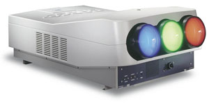
As per the pictures, the G2/diagnostic board has a row
of green LEDs on it along with one red LED, and an
additional separate green LED. The green LEDs all
grouped together monitor the main SMPS, and each LED
represents one voltage. All of the green LEDs should be
on when the set is turned on. One of those LEDs does not
come on until the set goes through a full diagnostic
check, about 5 seconds after power is turned on.
The single green LED away from the rest is to indicate a
working convergence power supply, which is located on
the G2/diagnostic board. If this green LED is not lit,
the set should fire up and show a picture, but the
convergence and geometry controls will have no effect.
There are 4 fuses on this board. Three are soldered in
place, the 4th is in the black plastic cylinder. Replace
with the same value fuse, if they continue to blow, the
board or something in the set has failed.
The G2 adjustments are the individual master brightness
controls for each tube. Mis-adjustment here will cause a
dim or washed out image. Please refer to the service
manual for the proper settings of these controls.

|
|

