Definitive CRT Projector Setup Guide |
(Page 3)
|
Page:
1 2
3 4
5 6
|
| |
Electronic focus
Once the electronic astigmatism has been completed, it’s onto the electronic
focusing.
It’s usually best to use the H focus pattern within the NEC test patterns,
although some techs may prefer to use other or external patterns. I’ve also had
good results using the small text that are displayed under Windows icons. Simply
drag the icons around the computer screen, and use the small lettering to set
the focus.
The below photo shows a screen that is properly in focus. The H letters
should be uniformly in focus all over the screen. Note that there are three
focus trimpots that are labeled on the right side of the card cage, on the WAVE
board. One setup tech that is well known in the industry recommends that the
center electronic focus be set to -10, then each of the trimpots on the PC board
are set for the best center focus. That gives the edge and corner focus a touch
more range, which is always handy.
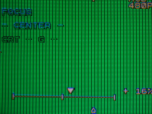
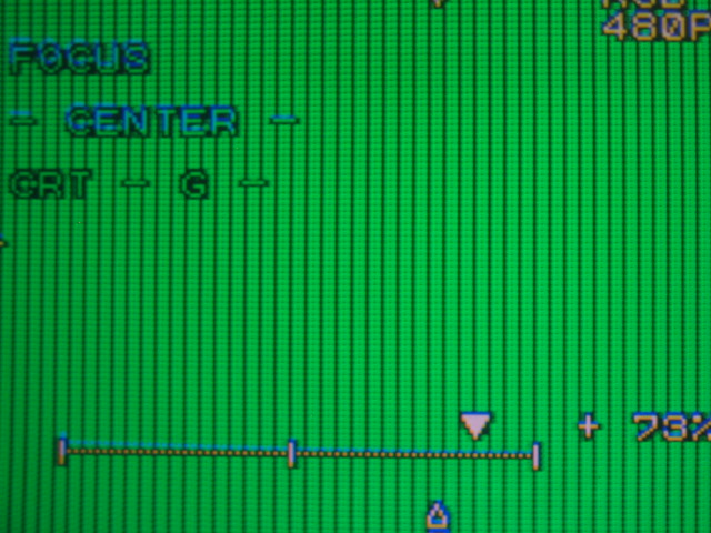
The below photo shows the approximate range of the center focus control It
should be pretty obvious when you run the center focus control from -100 to
+100. Try to have the best focus at about -10:
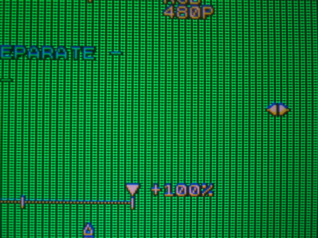
The edge and corner focus have much less range than the center focus, as with
the astig adjustments. Usually I find that the left and right edge focus need to
be high on the positive side, something between +50 and +90. The top and bottom
focus controls are usually not set anywhere near that high, but whatever
settings work to get the best focus is what they should be at:
Repeat the above for all sides and corners and for all colors, and you’re set
to go!
OK, now that the geometry is hopefully aligned well, and you have a square
looking grid pattern on the screen for the green tube, it’s time to align the
red and blue tubes over the green.
Fortunately you’ve learned almost all of the parameters already that you need
for the red and blue convergence, we’ll do a summary here. For simplicity’s
sake, I’m only showing the red convergence setup. The blue setup and controls
are identical to the red convergence.
You’ll probably find that some convergence controls will slightly affect
other parameters. Often you’ll need to go back to other parameters and ‘nudge’
the settings slightly to bring them back to perfection. This is common for all
CRT projectors. Practice makes perfect!
Geometry
OK, so now that we have the tubes focused and the rasters centered and the
tube toe-in done, we need to start with the geometry setup. AS with most
projectors, the NECs are best done in sequence that the manual says, but since
no one seems to read the manual, I’ll also say that the remote control has the
controls set up in a logical fashion from top to bottom, ie, skew, bow, height,
lin, keystone and pin. Follow those top to bottom and you’ll get a good start on
setting up the NEC. The following is a basic guide to getting good geometry on
the NEC.
The Geometry controls are used to set up the green tube as it is the tube
that the red and blue are referenced to. Any adjustments made to the geometry
menu will also affect the red and blue tubes. Once you go into the convergence
menus to adjust the R and B colors, those convergence adjustments will only
affect the red or the blue tube, whichever color is selected.
So let’s look at what the basic geometry controls do.
Tilt and Skew
Here are examples of what the tilt and skew do. They tilt the image in a
horizontal and vertical direction and affect the ENTIRE picture. Generally
speaking, the tilt and skew should be fairly close to the midpoint, but slight
shifts in ceilings can tilt the projector slightly so that correction is
required to level the picture perfectly. Use the horizontal and vertical lines
in the middle of the grid as a reference. If you want, mark the middle of the
screen at the top, bottom and sides with a measuring tape and masking tape to
make sure the center lines are exactly level.
Too much vertical skew:

Too much skew in the opposite direction:

Too much H tilt:

Just right!

In my shop, the floor is slightly skewed (it’s a garage), so my tilt and skew
are slightly off center to make the image level. Even when a set is installed
perfectly, it’s quite possible for any number of parameters not to be exactly at
the 0 mark.
Bow
As with the SKEW and TILT controls, the BOW control bends the entire image up
or down and left and right. Again, concentrate on the middle lines in a
horizontal and vertical plane to get the lines as straight as possible.
Too much vertical bow:

Too much in the opposite direction:

Again, generally speaking, the bow controls should be fairly close to the
midpoint to get a straight line in both vertical and horizontal directions.
Amplitude:
The AMPLITUDE control acts as the horizontal and vertical size. Too low of a
setting and the picture won’t fill the screen. Too high of a setting and you’ll
overshoot the screen.
Too little H and V amplitude:

Just about the right amount of amplitude. The test patterns overshoot the
screen slightly, which means that the actual image should fit just into the
screen with minimal overshoot onto the black borders:


|
