 |
||||||||||||
| Home |
|
Products For Sale |
FAQs, Tips, Manuals |
Referral List |
|
Photo Gallery |
|
Links |
|
Contact Us |
|
|
||||||||||||||||
Note:
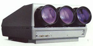
All LED’s in Barcos are color coded. Here is a breakdown of one of the more popular projector chassis out there. I’ve sold dozens, if not a couple of hundred of these. You’ll note that the chassis of all of the Barco 800/801 series are very similar, and some parts and modules can be interchanged between sets. The Barco 800 layout and setup tips guide can also be used for the 801 chassis. This guide can also be used for the Barco 500 series that used the smaller 7” tubes. The chassis of the 500 and 800 is identical but the 500 does not have a built in wired keypad. A keypad from an 800 or 801 may be installed into a 500 chassis as the plug in for the keypad is on the motherboard, it just isn’t being used.
The keypad is plugged into the motherboard where the rear IR connector is located. The wired keypad may be lengthened up to 25 ‘ or so with a 4 conductor cable if desired.
Below these general layouts are board specific pictures and descriptions. If a trimpot or adjustment is not labelled, it’s not meant for a consumer level adjustment. Proceed at our own risk!
Again, the layout of the Barco 500, 800, 801 and 808 sets are very similar as you can see from the pictures
The Barco convergence tray pulls out from under the tubes. Loosen the large slot screws on each side of the board, and pull out the metal plate. The convergence board is connected to it, and will pull out with the metal plate. You’ll probably have to loosen the screws a bit, then pull out the board a bit, loosen a bit more, etc, as the screws will start to pull out the metal plate. You’ll notice when the screws are loose, they will spin, but will not pull out completely as a washer behind the plate prevents the screws from coming out. When reinstalling the convergence board, make sure the PC board slides in on the plastic rails on each side. Also make sure that the 64 pin module connectors do not have any bent pins, as this can short out the convergence board or the power supply.
|
|
|||||||||||||||


© Copyright CurtPalme.com. All Rights Reserved. |