Latest News
Lumagen 8K-READY ArtisaN pre-order sale ends April 30, 2026
April 15, 2026
Last chance to save! The Lumagen 8K-READY ArtisaN video processor pre-order sale ends April 30, 2026. These are expected to start shipping in June 2026. Trade-ins available. For specs and details on the ArtisaN including how it compares the existing Radiance Pro line, see our updated Radiance Pro/ArtisaN page. Prices are too low to advertise, please contact us for details.
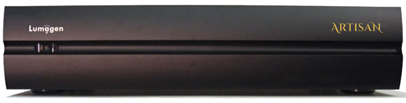
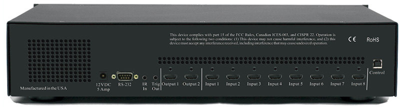
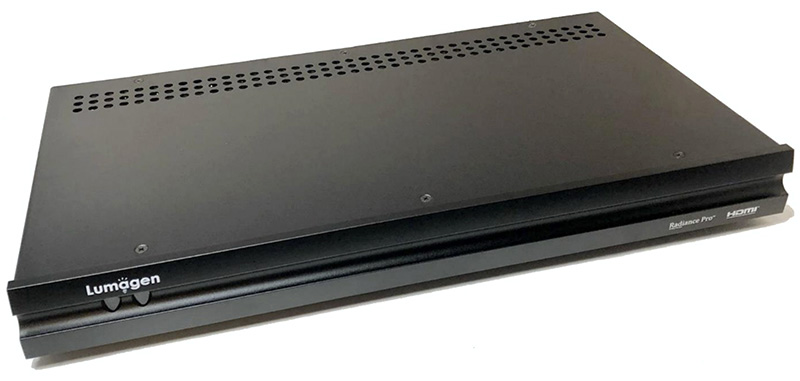
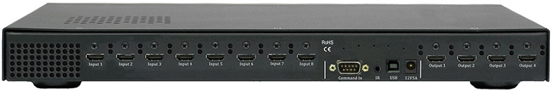
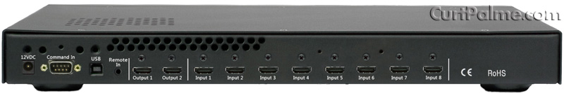
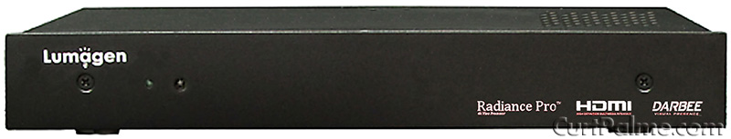
The Lumagen ArtisaN 8K-READY video processor is designed for home cinema use and offers video processing capabilities that support up to 8K60 and 4K120. The Artisan includes support for HDCP 2.3, HDR10, and HLG, and is compatible with Dolby LLDV sources. It features eight inputs, two outputs, and a range of video processing, setup, and calibration options. A new backlit remote and rack ears are included.
At launch the ArtisaN will support up to 4K60 processing on all inputs and outputs. Upgrade options that will become available shortly after are:
-
Add Lumagen's HDMI 2.1, 8K and 4K120 Input & Output Passthrough (switching only) Upgrade for $500 (USD)
-
Upgrade to the full Artisan 8K version. This includes Lumagen's HDMI 2.1, 8K and 4K120 Input & Output Processing for $2,000 (USD)
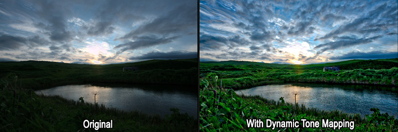
The Artisan builds upon Lumagen's Radiance Pro series, maintaining all the existing features of that series while adding new functionality. One such feature is the ability to control Seymour-Screen Excellence's masking systems. Lumagen's proprietary Dynamic Tone Mapping (DTM) technology, which optimizes images on a per-frame basis, has been refined for the Artisan.
The new processor also addresses scaling quality for 8K projectors and televisions, using Tektronix PQA600C analysis software for various video resolutions, including 4K and lower. An edge-sharpening feature is included to restore detail lost during compression.
To reduce HDMI output clock jitter, the Artisan uses specialized circuitry similar to the Radiance Pro 5244/5348, which is said to improve audio quality by minimizing distortion at the DACs. The processor uses FPGA technology to allow for future upgrades.
Interested in pre-ordering a Lumagen ArtisaN or have questions? Email
kal@curtpalme.com
Limited supply of Radiance Pro 42xx B-stock units
available
February 17, 2026
We have a limited number of discounted Radiance Pro 42xx B-stock units
available for order, including 4240-C+, 4240-C-18G, 4240+, and 4240-18G models. For specs and details see our Radiance Pro/ArtisaN page. Pricing is too low to advertise so please
contact us for details. Functionality is identical to new (A-stock) units,
these are simply open box or gently used. They have all been reviewed / tested
by the manufacturer and ship directly from them with full
support and 2-year warranty just like new (A-stock) units. Optional extended
warranty up to 5 years also available. Supply is extremely limited. These do not come up often
(last time was 2 years ago) and the popular models always sell out quickly!
Interested in a discounted Radiance Pro 42xx B-stock unit or
have questions? Email
kal@curtpalme.com
Murideo SIX-G 8K Video Test Pattern Generator now
available
Mar
3, 2023
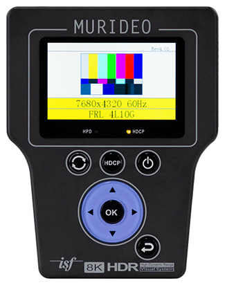
Everyone’s favorite HDMI test device received an 8K overhaul. The 8K SIX-G
from Murideo is beyond a test pattern generator. It is an essential tool for
anyone working with HDMI. Able to produce video signals up to 40Gbps allowing
you to test any 8K capable HDMI product, including 8K TVs, sources, AVR’s, and
projectors.
- Ideal for Modern Display Calibration
- 40Gbps Maximum Bandwidth
- 8K60 (4:2:0) 10-bit
- Full HDR, Dolby Vision, HDR10+ and HLG support
- EDID Read Functionality
- Imaging Science Foundation Certified
The Murideo 8K SIX-G is an HDMI pattern generator intended for the AV
integration market to confirm HDMI 2.1 and HDCP 2.3 / 1.4 operation at the 40Gbps
level. This device can create a signal that allows it to act as any modern HDMI
source. Additionally, the SIX-G is an excellent field troubleshooting tool for
distributed high bandwidth HDMI systems and a reference source for video
calibration.
The handheld device is portable thanks to a built-in battery and can generate
over 100 different test patterns for setup, calibration, and troubleshooting.
There’s a three-inch color display with simplified menus as well as free PC
control software. The 8K SIX-G also features Hot Plug Detect, EDID read/write
functionality, and the ability to create custom resolutions. There’s the option
for either RS232 or USB control and support for Calman and Light Illusion
calibration software. The 8K SIX-G is the only unit to carry the complete suite
of ISF test patterns, select-able color output level, RGB Triplets, and Constant
APL (Average Picture Level) all in one place. The 8K SIX-G is a calibrator’s
dream because it’s: ISF Labs certified, the firmware is field upgradable, and it
even includes audio confidence tests.
Supported by
ChromaPure Professional.
Questions? Email us at:
chromapure@curtpalme.com
More Information »
CRT Projector Parts Liquidation
April 18, 2022
After almost 40 years of doing CRT projector
sales and service, the time has come to liquidate
all remaining CRT projector parts!
We have in stock a vast selection of 9" tubes,
from light wear to really good used condition, as
well as a couple of NOS (new old stock) tubes still
in boxes. We are now officially sold out of all
projector parts with the exception of Barco
909/Runco DTV 1200 models, and no longer have any
complete sets to sell, sorry!
We have started listing all remaining parts
through our
ebay listings, however a
20% discount applies if you buy outside of ebay. For
boards we will combine shipping but tubes must be
shipped in individual boxes to reduce the risk of
damage in transit.
Coming soon to our
ebay listings
will also be a Barco 909
test chassis that will include the following:
- Barco chassis, less
a working controller module (the one in the set
powers up but has some adjustment issues). Two of
the CRT video amplifiers are also missing.
- An (almost) one of
a kind Barco module extender board that allows the
tray under the tubes/lenses to come out for
servicing.
- An original Barco 909 service manual, with
notes in it from Curt.
- As many defective 909 boards as
you want. Most can be repaired, some have been
robbed of some parts.
- A 'regular' module extender
kit, to bring all other modules up and out of the
card cage for servicing.
Email Curt for details for any
of the above, and check our
ebay listings
often as new items will be added periodically as we clean house, including
approximately 30 more tubes, additional CRT parts, and original service manuals.
There are still lots of Barco 909s out there in the field, so if you want to
take on the worldwide servicing of these projectors (or service your own) this
is a great way to do it.
A big thank you to everyone that has supported
our CRT projector sales and servicing over the last
few decades! When we discovered ebay in 1999, we
never expected to turn our love of CRT projectors
into an actual business, let alone travel all over
North America seeing all sorts of great home and
commercial CRT installations.
If you're into vintage reel to reel tape
recorders at all, check out our newest website too:
ReelToReelTech.com
Cheers!
Questions?
Email
Curt@CurtPalme.com
See our ebay listings »
New Radiance Pro
5244
December 15, 2021

The Radiance Pro 5244 is the newest in a long line of Radiance video processors
and features 6 x 18 Ghz HDMI inputs, 1 x 18Ghz HDMI outputs, and 1 audio-only
output.
What sets the Radiance Pro 5XXX series apart from previous 4XXX models is the electrical improvements in the
design. While using the same HDMI chips, and FPGA, the use of linear regulators
for 28 critical power supplies, and the addition of an HDMI dejitter output
buffer, has dramatically reduced output jitter and noise. The use of Faraday
cages for all nine DC-to-DC switching-regulators dramatically reduces EMI. As an
example, the current 18 GHz Rev 1.4 output card in a 4XXX has a HDMI data jitter
of about 80 pS (HDMI specification requires 102 pS or less for 18 GHz). In
comparison the measured HDMI output data jitter on the Radiance Pro 5XXX is 45
pS, or just about half. More importantly for audio, the HDMI output clock jitter
has been measured at about 10 pS. This is a nearly ideal clock to send to the
audio processor.
People have asked if reduced jitter and electrical noise matters. Yes,
it does. Based on A-to-B testing with the Lumagen Demo Theater’s Trinnov
Altitude 16, the Radiance Pro 5XXX does make a significant improvement for
appropriate content (e.g. Greatest Showman “Never Enough”). Some have asked
about the current 4XXX product line: “The Radiance Pro does not process audio.
So how come audio sounds better when it is running through the Radiance Pro?”
The difference is lower jitter and reduced electrical noise. The Radiance Pro
4XXX output jitter and electrical noise are already dramatically better than
other products we know about, but the 5XXX takes jitter and noise reduction to
what we consider is the ultimate audiophile level. For complete details see our
Radiance order page.
About the Radiance Pro
Looking to add the best video processor available today to your high end 4K /
HDR home theater? The Lumagen Radiance Pro is what you need to ensure the best
image quality possible.
The Radiance Pro series improves on the award-winning Radiance video processor
family by adding support for 4k60 inputs, and outputs, including HDCP 2.2,
HDR10, and HLG. Winner of a CEPro Best of 2015 award, and a Best Video Product
award in Australia in 2019, the Radiance Pro is not standing still. Lumagen is
adding to its 20-year legacy of video processor development by continuing to
enhance features and algorithms with software updates.
The Radiance Pro family offers up to ten inputs, four outputs, and a multitude
of processing, setup, and calibration features. Much more than an HDMI switcher,
the Radiance Pro has a host of features to improve the image on your screen. It
is considered by many experts to be an essential part of any quality home
theater.
Optimizing HDR content has perhaps become the most important video processing
feature. The Radiance Pro Dynamic Tone Mapping (DTM) analyzes every frame of
content for multiple regions of each frame, detects scene changes, and optimizes
the “transfer function” for each frame of content. Jon Thompson, a movie
producer who is responsible for post-production image quality at a major studio,
recently evaluated the Radiance Pro DTM versus the other DTM options. He said
that "the other DTM options are not even in the same league as the Radiance
Pro."
Scaling quality again comes to the forefront with the advent of 4k projectors
and televisions. Lumagen’s NoRing™ scaling provides the best quality scaling for
1080, 720, and SD, sources for 4k projectors and TVs. Scaling is also essential
for aspect-ratio control, especially when using an anamorphic lens. In addition,
the Radiance Pro has a edge-sharpening feature that helps restore detail lost
during compression of the digital content.
Reference quality colorimetry is often overlooked as part of a high-end home
theater. The Radiance Pro can provide automated video equalization, using third
party calibration software, with more accuracy than calibration without a 3D
LUT. Using the Radiance Pro’s Color Management System, you can see what the
director intended.
Other features include anamorphic screen support for HD, 3D, and 4k UHD and HDR
sources, with or without an anamorphic lens. Image based auto-aspect selection,
plus precise geometry adjustments including size, and masking, are available.
The Radiance Pro’s Non-Linear-Stretch (NLS) feature allows the user to stretch
16:9 content to fill an anamorphic screen using their preferred settings. For
16:9 screens and TVs, an anamorphic image can be placed anywhere in the active
screen area, or with some zoom, and/or cropping, can fill a larger portion of
the screen. Multiple configuration memories allow for multiple independent
configurations, such as day, night, sports, and black-and-white. For 4XXX
models, dual-port I/O cards can be upgraded from 9 GHz to 18 GHz in the field.
The Radiance Pro 5XXX models have a fixed I/O configuration.
The adaptability of the Radiance Pro is second to none. Using Field Programmable
Gate Array (FPGA) technology, the Radiance Pro can add hardware image processing
and setup features long after installation. The Radiance Pro is adding new
features over time. One example is HDR video, which did not even exist at
introduction. DTM was added four years after product introduction and is
available to all Radiance Pro owners by simply updating to the latest release.
Your Radiance Pro’s feature-set and performance are "only as old as its most
recent software release."
Extra $500 off advanced auto-calibration package
The $500 discount on our
advanced auto-calibration package also applies to
our Radiance Pro 5244 sale. Advanced
auto-calibration allows anyone with little or no
training to fully calibrate their display with
almost no user input to almost 5000 points. It
adjusts the display's grayscale, gamma, and colours
to levels of accuracy that are simply not achievable
by manual (hands on) methods. Just setup a few
simple options in the included
ChromaPure
software, click "Auto-Calibrate", and then go have a
cup of coffee while the process completes. There is
no need for the user to understand how calibration
works. Suitable for all display types from the
oldest CRT projectors to the newest OLED TVs and
laser projectors.
For a complete breakdown of Radiance models, see
our newly updated
Radiance feature comparison table.
Questions? Email
kal@curtpalme.com
More Information »
Radiance extended warranties available
October 22, 2021
Manufacturer extended warranties on
Lumagen Radiance video
processors are now available, taking the 1 year
warranty to 5 years from the date it was shipped
from Lumagen.
The warranty terms and conditions are the same as
before, and can be found in the first few pages of
your Radiance manual. The only difference is
that the time is extended from 1 year to 5. The
extended warranty is transferrable to a new owner if
the unit is sold.
Available for units purchased new,
units still under their 1 year warranty, and in some cases for
units just out of warranty (at the manufacturer's
discretion) assuming the unit is still functional.
Accidental damage, such as from a power surge, is
not covered.
Interested? Please
contact us with your Radiance model
number for pricing.
New batch of Moome Sony HDMI cards now shipping
August 25, 2021
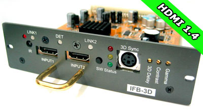
Moome's latest batch of IFB-FULLHD v3 HDMI cards for Sony CRT projectors
is now shipping! Supply is extremely limited, with
most of the cards already pre-sold.
These cards allow you to connect digital HDMI
devices such as Blu-Ray players, Playstation/Xbox gaming
consoles, AppleTV, and satellite/cable HDTV set-top
boxes to your Sony CRT projector.
Simply plug the card into your projector and
connect with an HDMI cable. All cards offer IR
remote control and advanced features such as gamma
correction for perfect shadow detail.
Questions? Email us at
MoomeCard@CurtPalme.com.
More Information »
New Radiance Pro 5348
January 26, 2021
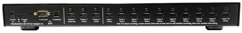
The Radiance Pro 5348 is the newest in a long line of Radiance video
processors and features 10 x 18 Ghz HDMI
inputs, 2 x 18Ghz HDMI
outputs, and 1 audio-only output.
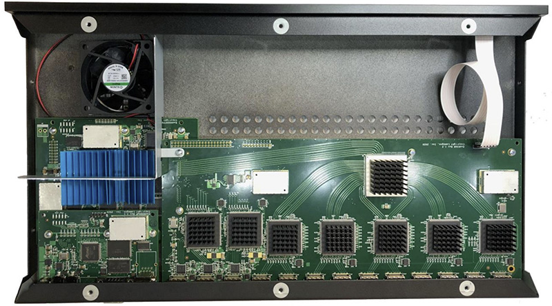
What sets the Radiance Pro 5348 apart from previous 4XXX models is the electrical improvements in the
design. While using the same HDMI chips, and FPGA, the use of linear regulators
for 28 critical power supplies, and the addition of an HDMI dejitter output
buffer, has dramatically reduced output jitter and noise. The use of Faraday
cages for all nine DC-to-DC switching-regulators dramatically reduces EMI. As an
example, the current 18 GHz Rev 1.4 output card in a 4446 has a HDMI data jitter
of about 80 pS (HDMI specification requires 102 pS or less for 18 GHz). In
comparison the measured HDMI output data jitter on the Radiance Pro 5348 is 45
pS, or just about half. More importantly for audio, the HDMI output clock jitter
has been measured at about 10 pS. This is a nearly ideal clock to send to the
audio processor.
People have asked if reduced jitter and electrical noise matters. Yes,
it does. Based on A-to-B testing with the Lumagen Demo Theater’s Trinnov
Altitude 16, the Radiance Pro 5348 does make a significant improvement for
appropriate content (e.g. Greatest Showman “Never Enough”). Some have asked
about the current 4XXX product line: “The Radiance Pro does not process audio.
So how come audio sounds better when it is running through the Radiance Pro?”
The difference is lower jitter and reduced electrical noise. The Radiance Pro
4XXX output jitter and electrical noise are already dramatically better than
other products we know about, but the 5348 takes jitter and noise reduction to
what we consider is the ultimate audiophile level. For complete details see our
Radiance order page.
Want to upgrade?
Trade-ins available against any Lumagen video processor (working or not).
Contact us for details.
Extra $500 off advanced auto-calibration package
The $500 discount on our
advanced auto-calibration package applies to
this new Radiance Pro 5348, same
as all other Radiance Pro units. Advanced
auto-calibration allows anyone with little or no
training to fully calibrate their display with
almost no user input to almost 5000 points. It
adjusts the display's grayscale, gamma, and colours
to levels of accuracy that are simply not achievable
by manual (hands on) methods. Just setup a few
simple options in the included
ChromaPure
software, click "Auto-Calibrate", and then go have a
cup of coffee while the process completes. There is
no need for the user to understand how calibration
works. Suitable for all display types.
For a complete breakdown of Radiance models, see
our newly updated
Radiance feature comparison table.
Questions? Email
kal@curtpalme.com
More Information »
New Radiance Pro 4244/4246 models, revamped
B-stock units
July 22, 2020
We are excited to announce the Radiance Pro 4244
(six input, two output), and the Radiance Pro 4246
(eight input, two output). Customers
have been asking for more inputs than the four the 4242
supports, but with only two outputs to keep cost
down. The Radiance Pro 4244, and 4246, fulfill this
request, and fill the price gap between the
4242 and the 4444.
The 4244 and 4246 use the
444X main board, but chips responsible for the
additional two outputs and picture in picture /
picture on picture (PiP/PoP) have been removed to save manufacturing cost. So, as with the 424X
models, the 4244 and 4246 do not support PiP/PoP. Like all other Radiance Pro units both models
are available in various 9Ghz or 18Ghz HDMI port
configurations, all of which support 4K
resolution.
These come with full 1 year manufacturer
warranty and support. See our
Radiance order page for complete details or
to order.
New B-stock units available
New B-stock units are available but as aways supply is extremely limited.
Includes a small number of 444X units that do not
have the latest microwave capacitor improvements
(only relevant for audio in our opinion, as jitter
is a bit higher - video is fine by not having the
microwave capacitors). We also have a small number
of Radiance 2143 units left - perfect for a 1080p
only setup where 4K isn't required. The 2143 has
been discontinued so once these are gone they are
gone for good as no more are being manufactured.
Contact us for details and B-stock pricing.
Extra $500 off advanced auto-calibration package
The $500 discount on our
advanced auto-calibration package still
applies to these new Radiance Pro models, same
as all other Radiance Pro units (including B-stock). Advanced
auto-calibration allows anyone with little or no
training to fully calibrate their display with
almost no user input to almost 5000 points. It
adjusts the display's grayscale, gamma, and colours
to levels of accuracy that are simply not achievable
by manual (hands on) methods. Just setup a few
simple options in the included
ChromaPure
software, click "Auto-Calibrate", and then go have a
cup of coffee while the process completes. There is
no need for the user to understand how calibration
works. Suitable for all display types.
For a complete breakdown of Radiance models, see
our newly updated
Radiance feature comparison table.
Questions? Email
kal@curtpalme.com
More Information »
Datacolor SpyderX colorimeters now shipping
September
3, 2019
Buy direct from our ChromaPure partner at
prices lower than buying off their own website! Same
product, same support, just more money in your
pocket at the end of the day.
ORDER NOW »
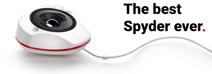
Recently introduced, the new SpyderX is by far the best Spyder
colorimeter Datacolor has ever offered. It provides
massive improvements in speed and low-light
sensitivity over previous Spyders. It's our new
recommended budget meter for those who do not need
to calibrate projectors and want a slightly lower
cost option to the
Display 3
PRO. If you have been interested in calibrating your
own displays but have been deterred by the high cost
of color meters and good software, this meter is for
you. Professional quality results at a non-pro
price.
We offer the
SpyderX PRO which takes the
regular SpyderX one step further and offers
professional grade accuracy at a price affordable to
the amateur hobbyist or enthusiast on over a dozen
display types including the newest OLED, Quantum Dot
(QLED), and Laser driven displays. Only available
when used with
ChromaPure.
For complete details on the performance of the
new SpyderX and how it compares to other popular
lower priced meters like the
X-Rite
i1Display Pro (Display 3) see our
SpyderX order page.
Questions? Email
kal@curtpalme.com.
More Information »
Moome HDMI card sale
September 3, 2019
Moome's having a sale on his
HDMI cards for CRT projectors (Sony,
Marquee, and
Barco).
These cards allow you to connect digital HDMI
devices such as Blu-Ray players, PS4/Xbox One gaming
consoles, AppleTV, and satellite/cable HDTV set-top
boxes to your CRT projector.
Simply plug the card into your projector and
connect with an HDMI cable. All cards offer IR
remote control and advanced features such as gamma
correction for perfect shadow detail.
Some models also add 3D functionality
(additional hardware is required - see our
HDMI card order pages for complete details).
Now's the perfect time to buy a backup as it's
unknown how much longer he will continue to offer
these products. Sale ends September 30. Free
worldwide priority shipping.
Questions? Email us at
MoomeCard@CurtPalme.com.
More Information »
Pre-Owned Radiance 2143 units available (limited
supply)
May
5, 2018
We have a very limited supply of pre-owned
Radiance 2143 video processors available at greatly
discounted prices. These units feature 8 HDMI
inputs, 2 HDMI outputs, no analog connections. These
are all in "like new" condition (they might have a
minor scratch but not on the front panel) and they
come with Lumagen's standard 1 year
limited-warranty. These units have all been fully
tested by Lumagen.
Contact us for pricing.
The Radiance 2143 is perfect for
advanced auto-calibration which allows anyone with little or no training to fully
calibrate their display with almost no user input to almost 5000 points.
It adjusts the display's grayscale, gamma, and colours to levels of accuracy that
are simply not achievable by manual (hands on) methods.
Just setup a few simple options in
ChromaPure
software, click "Auto-Calibrate", and then go have a cup of coffee while the
process completes.
There is no need for the user to understand how calibration works.
Suitable for all display types.
For a complete breakdown of how the Radiance
2143 compare to other models, see our
Radiance feature comparison table.
Interested? Email
kal@curtpalme.com for pricing.
More Information »
New Radiance Pro Models
January 31, 2018
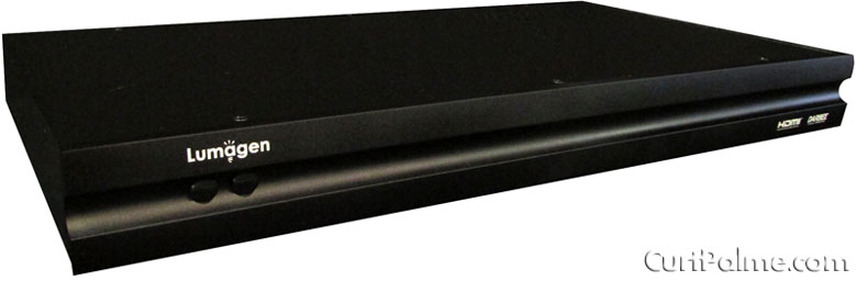
The new Radiance Pro 424X-C (compact model): Same features, smaller footprint
Radiance Pro 424X-C
Over the past months Lumagen has been asked for a
smaller version of the
Radiance Pro for use in smaller systems,
such as bedrooms that have limited space, or small
enough to easily carry to a calibration job. Because
of these requests they have added two new Radiance
Pro units to the line-up: The
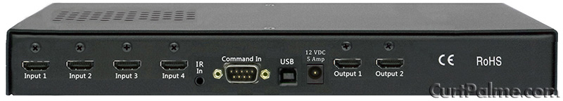
Radiance Pro 4240-C and 4242-C (pictures
above). The "-C" stands for "compact".
The 424X-C units are identical in hardware and
function, and uses the same software, as current
Radiance Pro 424X models. The only
difference is the size: These new units are 11.3"W x
5.25"D x 1.75"H while the full size models which are
17"W x 10"D x 1.75"H. The front is similar to the
Radiance 2020 except the IR sensor and LED have
moved, and there is a Radiance Pro logo added. The
back looks like the connector portion of the full
sized Radiance Pro 424X. Pricing remains the same as
the existing 424X models (while the case is smaller,
the cost is dominated by manufacturing labor and
production volume, and not material). 18 GHz
upgrades are still available just like the current
4XXX models.
These new units are perfect for use with 4K
panels where space may be limited but you still want
perfect video and calibration. Our limited time $500
off discount on our
advanced auto-calibration package still applies to these two new models, same as all
other Radiance Pro units. Advanced auto-calibration allows anyone with little or no training to fully
calibrate their display with almost no user input to almost 5000 points.
It adjusts the display's grayscale, gamma, and colours to levels of accuracy that
are simply not achievable by manual (hands on) methods.
Just setup a few simple options in
ChromaPure
software, click "Auto-Calibrate", and then go have a cup of coffee while the
process completes, usually in a few minutes.
There is no need for the user to understand how calibration works.
Suitable for all display types.
Radiance Pro 444X-1U
Lumagen has decided to transition to a 1U (1.75"
height) case for all Radiance Pro products, so they
have introduced
Radiance Pro 444X-1U models. The 2U
(3.5" height) chassis will remain the standard model
until stock is gone. If you prefer a 1U version, let
us know at the time of order.
Radiance 214X price drops
Effective immediately
Radiance 2143/2144 prices have been dropped
significantly, placing them $200 lower than the
previous 2123/2124 prices! The Radiance 2123 and
2124 have now been discontinued.
Like the Radiance 2020, supply on remaining
2144/2143 units is low. Once these are sold Lumagen
will not be building more. Focus will be on the
4K/HDR capable Radiance Pro series.
For a complete breakdown of how these Radiance
units compare to other models, see our
Radiance feature comparison table.
Questions? Email
kal@curtpalme.com
More Information »
Barco 909 / CRT Projector Parts Blowout
December 16, 2017
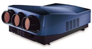
Barco 909
Over the holidays, I will be putting up a number
of Barco 909 projectors for sale at very attractive
pricing. I have 5 in stock, and the tube condition
and lenses will vary. I just took in a bunch of
Barco 1209s projectors on trade, including a couple
that have very low hour tubes in them, so I will be
retubing the sets that I have, and will price them
from $1500-$3000 USD, depending on tube condition
and the type of lenses on them. I have two sets of
the top of the line HFQ900 lenses, as well as the
more standard GT17 lenses, and a few sets of the
small screen HD10L ones as well. I do also have red
and green colored C elements that can be added to
any of these 909s.
If you’re interested
send me an email,
and I will contact you as I work through the
projectors, between Christmas and New Years. Remotes
are included, ceiling brackets are not. I do have
two ceiling brackets available at $150 USD each if
you need them. The 909 is the pinnacle of CRT, and I
personally use two 909s in a stacked configuration
in my own 10' wide theater.
CRT Projector Parts Blowout
I am liquidating many projector parts and tubes
as following:
Boards are $15 USD each plus shipping, minimum
order 4 boards. Boards are untested, but were
working when put on the shelf. I will not knowingly
sell defective boards here, in fact I'll throw a
defective board in as a freebie if you want it, as I
do have some that are clearly marked as having
issues.
The $15 each also applies to whatever tubes I
have here for 8" sets. Reds will be pristine, blues
and greens may have some wear, but I will indicate
such via email before I ship so you know what you're
getting. I will ship tubes separately, they will get
crushed if I pack them with PC boards.
The projector boards and tubes include:
- NEC XG
- NEC XGLC
- Barco 1208
- Barco 1209
- Barco 808
- Barco 70X series
- Barco 800/801 (I have almost nothing for
these sets at this point)
- Sony 12XX (almost nothing left)
- Sony 1292 (very limited stock at this point)
- Marquee non Ultra boards*
- Worn Barco 1209s tubes with mounting frames
- Worn Marquee 9500 tubes c/w yokes and
mounting frames. Very useful for upgrading to
LUG tubes while continuing to watch your
existing set.
*Most Marquee non Ultra CLMs will need the battery to be replaced, a new
battery is NOT included in the $15 price.
What is NOT included:
- Barco quadruplers and HV splitters
- Barco 909 chassis and derivatives thereof
(Cine 9, Runco 1200, etc)
- Sony G90 parts
- Marquee Ultra boards of any kind
- Marquee LV and HV power supplies
- Most other 9" parts
I will also sell a limited selection of Barco HV quadruplers and HV splitters
at $75 each untested, or $100 each, tested for 24 hours in a chassis prior to
shipping. I have about 5 of each available.
Please
email me, indicating what you're interested
in.
It will take me some time to respond, but I can
deal with most requests to get them out before
Christmas. I will be working in the shop like a
madman all through the holidays to catch up on my
backlog as well. My sound company day job (www.soundsolutionscanada.com)
has had me very busy since the beginning of June,
but it's finally starting to slow down, giving me
time to process CRT parts and projector orders. This
is a great way to stock up on spare boards, some of
which are getting hard to find. I will still support
CRT until the last one is pulled out of service/
(That will be my own two 909s on my ceiling!). I
still have test chassis, and still do many repairs
of boards every month.
Cheers!
See my
ebay summary for more listings.
Questions?
Email Curt.
See All CRT Projectors »
Old News »
|