| Author |
Message |
barclay66

Joined: 27 Jun 2011
Posts: 1304
Location: Germany
TV/Projector: Marquee 9500 Ultra
|
| Posted: Tue May 29, 2012 8:24 am Post subject: Marquee Control Expander |
|
|
Dear community,
Is there anyone that has a PDF of the Marquee's (8500/9500) optional decoder board schematics and would be willing sending it to me?
I'd like to take a look at it in order to find out about the I2C devices and addresses being used on it. At least there have to be some D/A converters (usually the TDA8444) for "Tint", "Detail" and "Color" and maybe some I/O device (usually the PCF8574). Each of them uses an individual I2C address which is set via programmable input pins (either tied to VCC or GND).
The Marquee will "believe" that a decoder board has been plugged in if it gets acknowledge messages from these addresses during startup. Then these devices could be used for controlling something completely different. I have some ideas:
- Control the gamma settings of a mounted Moome card via the Marquee's remote (e.g. using the values from the "Color" D/A). With some luck it could even be possible that the Marquee stores an individual level per defined channel. So You could have different settings per input channel. This would require modification on the Moome card as the analog trim pot would have to be replaced.
- Control an adjustable peaking circuit (e.g. using the values from the "Detail" D/A) which would have to be built on the VIM around switched capacitors. Individual settings per channel maybe possible too. I know that this could be very difficult. TSE's peaking circuit uses a capacitor in the Picofarad range. Any parasitic capacitances from the switches could lead to really bad results.
- Anything else I haven't thought of and would be nice being controllable.
So the basic idea would be building a controller board which plugs into the module bay where normally the decoder board goes into. Its output lines could be routed to other boards if there are some unused connector pins left. Otherwise additional wiring would be necessary.
These are just my ideas. If anyone knows they're bull**** then please speak up and tell me why. I'd save a lot of time otherwise spent on a fruitless project! Otherwise I'd like to give it a try...
Regards,
barclay66
Edit: Topic name changed
Last edited by barclay66 on Thu May 31, 2012 11:17 am; edited 1 time in total
|
|
| Back to top |
|
 |
Tim in Phoenix

Joined: 21 Oct 2006
Posts: 4409
Location: Phoenix
|
| Posted: Tue May 29, 2012 1:38 pm Post subject: |
|
|
Hello
Your ideas are good, but I cannot remember a decoder schematic ever being released from Electrohome.
.
|
|
| Back to top |
|
|
Nashou66

Joined: 12 Jan 2007
Posts: 16171
Location: West Seneca NY
|
|
| Back to top |
|
|
barclay66
Joined: 27 Jun 2011
Posts: 1304
Location: Germany
TV/Projector: Marquee 9500 Ultra
|
| Posted: Tue May 29, 2012 2:15 pm Post subject: |
|
|
| Nashou66 wrote: | | the service manual might mention which control lines go to the decoder board. |
Yes, it does. The schematics of the Backplane Mother Board show the connector with its signals. The I2C bus is present.
| Nashou66 wrote: | | But i bet TSE might have one. |
I Hope so. Cut-outs showing the devices connected to the I2C bus ("SCL" & "SDA") and those connected to the "INT" signal would be sufficient...
Regards,
barclay66
|
|
| Back to top |
|
|
barclay66
Joined: 27 Jun 2011
Posts: 1304
Location: Germany
TV/Projector: Marquee 9500 Ultra
|
| Posted: Tue May 29, 2012 2:29 pm Post subject: Re: Marquee Decoder Board Schematics |
|
|
| barclay66 wrote: | | - Control an adjustable peaking circuit (e.g. using the values from the "Detail" D/A) which would have to be built on the VIM around switched capacitors. Individual settings per channel maybe possible too. I know that this could be very difficult. TSE's peaking circuit uses a capacitor in the Picofarad range. Any parasitic capacitances from the switches could lead to really bad results. |
Difficulty for this one has just been reduced dramatically. Take a look at this device: http://psemi.com/content/products/DTC/PE64905.html
Regards,
barclay66
|
|
| Back to top |
|
|
tse
Joined: 03 May 2006
Posts: 1014
Location: Sweatbucket, Fl.
|
| Posted: Tue May 29, 2012 8:10 pm Post subject: |
|
|
These schematics are for the decoder that plugs into the slot above the VIM. There are a couple of I2C parts on the board. It looks like the module ID goes out on the I2C bus and is set with a couple of jumpers (just guessing).
Good luck,
Scott
| Description: |
|

Download |
| Filename: |
decoder_1.pdf |
| Filesize: |
69.65 KB |
| Downloaded: |
424 Time(s) |
| Description: |
|
Download |
| Filename: |
decoder_2.pdf |
| Filesize: |
59.02 KB |
| Downloaded: |
454 Time(s) |
| Description: |
|
Download |
| Filename: |
decoder_3.pdf |
| Filesize: |
72.91 KB |
| Downloaded: |
427 Time(s) |
| Description: |
|
Download |
| Filename: |
decoder_4.pdf |
| Filesize: |
53.82 KB |
| Downloaded: |
389 Time(s) |
| Description: |
|
Download |
| Filename: |
decoder_5.pdf |
| Filesize: |
52.31 KB |
| Downloaded: |
419 Time(s) |
| Description: |
|
Download |
| Filename: |
decoder_6.pdf |
| Filesize: |
45.94 KB |
| Downloaded: |
403 Time(s) |
_________________
"Were we directed from Washington when to sow and when to reap, we would soon want bread."
Thomas Jefferson
|
|
| Back to top |
|
|
barclay66
Joined: 27 Jun 2011
Posts: 1304
Location: Germany
TV/Projector: Marquee 9500 Ultra
|
| Posted: Tue May 29, 2012 10:32 pm Post subject: |
|
|
Excellent! Thank You very much Scott!
Everything needed can be seen on Sheet 3. There is one PCF8574 (U26) and one TDA8444 (U27). That's all for the I2C bus. If both are present with their respective addresses, the Decoder Board should be shown as present. On the TDA8444 You can see the three analog outputs for "Color", "Tint" and "Detail". Interestingly those are converted back to digital! Seems as if they weren't able to locate a device with digital output (I2C to parallel decoder).
Let me work on this an I'll see what can be accomplished. Unfortunately I will be away for a vacation next week so don't expect results too soon...
Regards,
barclay66
|
|
| Back to top |
|
|
tse
Joined: 03 May 2006
Posts: 1014
Location: Sweatbucket, Fl.
|
| Posted: Tue May 29, 2012 11:27 pm Post subject: |
|
|
I do believe that the ID (so the CLM knows the decoder is present) is placed on U26-9, 10, 11, and 12 and read on boot-up. JPR1 is installed so a 0 on pin 11. Pin 12 is pulled high. Your guess is as good as mine for pins 9 and 10. Not too many combinations thouogh so should be easy to find.
Scott
_________________
"Were we directed from Washington when to sow and when to reap, we would soon want bread."
Thomas Jefferson
|
|
| Back to top |
|
|
barclay66
Joined: 27 Jun 2011
Posts: 1304
Location: Germany
TV/Projector: Marquee 9500 Ultra
|
| Posted: Tue May 29, 2012 11:44 pm Post subject: |
|
|
Seems logical. The datasheets will reveal the rest. Thanks again Scott!
Regards,
barclay66
|
|
| Back to top |
|
|
tse
Joined: 03 May 2006
Posts: 1014
Location: Sweatbucket, Fl.
|
| Posted: Tue May 29, 2012 11:54 pm Post subject: Re: Marquee Decoder Board Schematics |
|
|
| barclay66 wrote: | | barclay66 wrote: | | - Control an adjustable peaking circuit (e.g. using the values from the "Detail" D/A) which would have to be built on the VIM around switched capacitors. Individual settings per channel maybe possible too. I know that this could be very difficult. TSE's peaking circuit uses a capacitor in the Picofarad range. Any parasitic capacitances from the switches could lead to really bad results. |
Difficulty for this one has just been reduced dramatically. Take a look at this device: http://psemi.com/content/products/DTC/PE64905.html
Regards,
barclay66 |
Something like this should work. Replace pot with a DAC. One or three channels could be controlled with the same voltage.
Scott
| Description: |
|
Download |
| Filename: |
VCPeak.pdf |
| Filesize: |
7.14 KB |
| Downloaded: |
435 Time(s) |
_________________
"Were we directed from Washington when to sow and when to reap, we would soon want bread."
Thomas Jefferson
|
|
| Back to top |
|
|
barclay66
Joined: 27 Jun 2011
Posts: 1304
Location: Germany
TV/Projector: Marquee 9500 Ultra
|
| Posted: Wed May 30, 2012 6:34 am Post subject: |
|
|
Excellent!
I'll start cannibalizing some Tuner modules I have lying around for varactor diodes...
Regards,
barclay66
|
|
| Back to top |
|
|
barclay66
Joined: 27 Jun 2011
Posts: 1304
Location: Germany
TV/Projector: Marquee 9500 Ultra
|
| Posted: Wed May 30, 2012 11:48 am Post subject: |
|
|
| tse wrote: | I do believe that the ID (so the CLM knows the decoder is present) is placed on U26-9, 10, 11, and 12 and read on boot-up. JPR1 is installed so a 0 on pin 11. Pin 12 is pulled high. Your guess is as good as mine for pins 9 and 10. Not too many combinations thouogh so should be easy to find.
Scott |
Hello Scott,
It's much easier than suspected. Each of the devices has three inputs for address selection. On U26 (PCF8574) those are Pins 1, 2 and 3 (A0/A1/A2). On U27 (TDA8444) those are Pins 7, 8 and 9. So I'm going to build a prototype board with only these two devices and their address settings, plug it into the decoder slot and see what happens...
Regards,
barclay66
|
|
| Back to top |
|
|
tse
Joined: 03 May 2006
Posts: 1014
Location: Sweatbucket, Fl.
|
| Posted: Wed May 30, 2012 1:05 pm Post subject: |
|
|
The chip addresses are set that way but the CLM has to know what board is plugged in to talk to the right parts. Attached is part of schem for a different decoder (this one doesn't have a TDA8444 so is less useful) showing how the CLM can determine which module to deal with.
Scott
| Description: |
|
Download |
| Filename: |
ID.pdf |
| Filesize: |
35.24 KB |
| Downloaded: |
411 Time(s) |
_________________
"Were we directed from Washington when to sow and when to reap, we would soon want bread."
Thomas Jefferson
|
|
| Back to top |
|
|
macgyver655
Joined: 22 Aug 2007
Posts: 8508
|
| Posted: Wed May 30, 2012 1:44 pm Post subject: |
|
|
|
Altho I'm not sure exactly what your trying to do and I'm not real familiar with the Marquee menu controls, I thought i might point out the in most displays these controls functions are only active if using a composite or S-video input and are disabled during RGB use. And I think that entire decoder board is inactive during RGB. Just thought I'd mention this.
|
|
| Back to top |
|
|
barclay66
Joined: 27 Jun 2011
Posts: 1304
Location: Germany
TV/Projector: Marquee 9500 Ultra
|
| Posted: Wed May 30, 2012 2:23 pm Post subject: |
|
|
@Scott:
This other Decoder board is not too different to the first one with regards to addressable I2C devices. The PCF8574A is just the same with the same I2C address and the second I2C device is now a MCU (80C652).
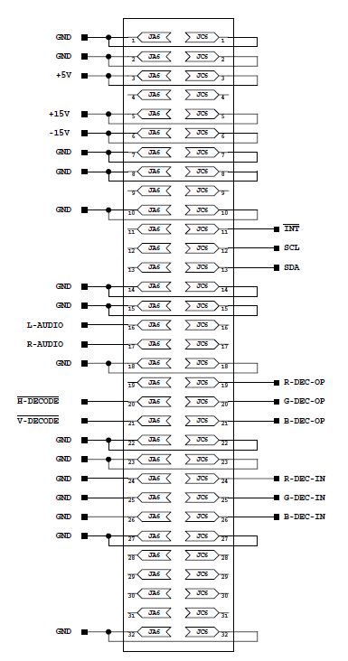
I really don't think that the Marquee has any means of detecting the board other than the acknowledge messages on the I2C bus. If You take a look at the Mainboard connector it becomes apparent that there are no sensing lines for board detection present. Please refer to the picture attached. In any case, I'll try as mentioned before and the decoder board will be shown on the status message screen or not. If not I'll try something else.
I'm sticking with my idea because in Barco projectors it is exactly the same. And too, it's an easy and convenient method. Just scan all known I2C addresses and listen for acknowledge messages. Boards that are present will answer. If the answer is only partial then throw an error message.
@macgyver:
I don't have a decoder board and run the RGB input only. Still I do get a message for "Color", "Tint" and "Detail" when I press the correspondent keys on the remote. And I can change the value that is displayed. What I will have to find out is if these actions do really change the corresponding output voltage at the D/A converter and if those values are being stored.
Regards,
barclay66
| Description: |
|
| Filesize: |
61.82 KB |
| Viewed: |
10034 Time(s) |
|
|
|
| Back to top |
|
|
Curt Palme
CRT Tech
Joined: 08 Mar 2006
Posts: 24396
Location: Langley, BC
TV/Projector: All of them!
|
| Posted: Wed May 30, 2012 2:27 pm Post subject: |
|
|
|
If anyone wants video decorder boards, I have at least 10 here that you can have for the cost of shipping. About 3 different versions, from the originals to the last SMT style.
|
|
| Back to top |
|
|
Tim in Phoenix
Joined: 21 Oct 2006
Posts: 4409
Location: Phoenix
|
| Posted: Wed May 30, 2012 4:46 pm Post subject: |
|
|
Guys
If someone were to build an adapter that placed the Moome card in the decoder slot, that might make things easier. The backplane might want composite sync, someone needs to look at that.
.
|
|
| Back to top |
|
|
barclay66
Joined: 27 Jun 2011
Posts: 1304
Location: Germany
TV/Projector: Marquee 9500 Ultra
|
| Posted: Wed May 30, 2012 8:54 pm Post subject: |
|
|
Hi,
My idea seems to work!
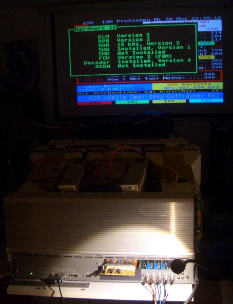
I built a board around the PCF8574A and the TDA8444 and plugged it in. Now the Marquee thinks it has a Decoder board installed! So I would assume the I2C recognition theory is correct. Take a look at the photos below.
You can see the board installed on an extender card inside the Decoder slot and the Diagnostic display indicating the installed boards.
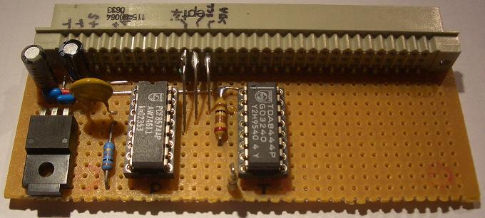
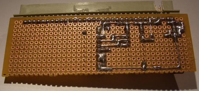
Furthermore You can see detail pictures of the board itself. I know: Quick & Dirty... But this is a first test and took me two hours only.
What's next:
- Verify that the analog Outputs are active and can be controlled
- Check which settings (Color, Tint & Detail) are stored under which circumstances
- Optimize the board and draw a schematic
- Build & test the adapting circuits for controlling the features desired
- Document everything
All of this has to wait until I return from my vacation after June 10th.
Regards,
barclay66
| Description: |
|
| Filesize: |
35.32 KB |
| Viewed: |
10002 Time(s) |
|
| Description: |
|
| Filesize: |
40.53 KB |
| Viewed: |
10000 Time(s) |
|
| Description: |
|
| Filesize: |
48.01 KB |
| Viewed: |
10000 Time(s) |
|
|
|
| Back to top |
|
|
Nashou66
Joined: 12 Jan 2007
Posts: 16171
Location: West Seneca NY
|
|
| Back to top |
|
|
Nashou66
Joined: 12 Jan 2007
Posts: 16171
Location: West Seneca NY
|
|
| Back to top |
|
|
|
|


