| Author |
Message |
listenlounge
Joined: 29 Apr 2007
Posts: 48
Location: NSW, Australia
|
| Posted: Sun Aug 19, 2007 12:23 am Post subject: No Standby pwr LED on Marquee 8000/8500 blend |
|
|
Hey guys,
Just got some mod'ed parts back from our friend with the burnt hand.
Reseated the CLM, LVPS, HDM and plugged the power in.
LVPS relays clicked on, Fans started to spin at the normal slow rate.
Remote control could not turn the unit on - checked the CLM - no standby ( orange ) LED.
Ideas?
Have tried reseating both CLM and LVPS and cleaning contacts....
HELP!
Ben
|
|
| Back to top |
|
 |
Tim in Phoenix

Joined: 21 Oct 2006
Posts: 4409
Location: Phoenix
|
| Posted: Sun Aug 19, 2007 12:33 am Post subject: |
|
|
Hello
If you have a wired keypad installed by the lenses, pop the battery door cover and unplug the wire, then see if Standby orange LED is lit. If no good, unplug power cord and pull Acon and Color Correction boards if installed, retry powerup.
If no good, then take the sides off next to the red tube. You will see wires routed under the tube for Acon camera, IR sensor, and wired keypad. If they are held to the frame with a tie wrap, cut the tie wrap and inspect the wires for cuts. Try unplugging the Acon cable connector from the backplane. Try also unplugging the IR sensor and try powerup with the wired keypad, and try unplugging the wired keypad and try powering up with IR. You either have something bad in the LVPS, the wiring from LVPS to the backplane, or a shorted device somewhere is holding down your Standby Power. We have seen shorted IR sensors, shorted wires against the sheet metal, there is a sharp edge visible in the picture where wires are secured in assembly, and shorted wired keypads all cause the sort of problem you are seeing there.

|
|
| Back to top |
|
|
tse
Joined: 03 May 2006
Posts: 1014
Location: Sweatbucket, Fl.
|
| Posted: Sun Aug 19, 2007 1:17 am Post subject: |
|
|
Does the "C" LED on the CLM flash when you press the power button? How about the LED on the remote control?
Scott
_________________
"Were we directed from Washington when to sow and when to reap, we would soon want bread."
Thomas Jefferson
|
|
| Back to top |
|
|
listenlounge
Joined: 29 Apr 2007
Posts: 48
Location: NSW, Australia
|
| Posted: Sun Aug 19, 2007 1:51 am Post subject: |
|
|
Thanks Guys for the ideas so far.
Let me answer some of the questions
I only have an IR remote - no hardwired - the lead for the hardwired remote has been removed from the machine and is not even present.
I do not have an ACON installed, but the cable is still present and plugged in correctly.
No lights at all on the CLM at any time.
LED does come on on the IR remote when any key is pressed.
Tim - Can I test for standby voltage where the wiring loom from the LVPS connects to the backplane? If so - which pins can I test?
|
|
| Back to top |
|
|
listenlounge
Joined: 29 Apr 2007
Posts: 48
Location: NSW, Australia
|
| Posted: Sun Aug 19, 2007 5:16 am Post subject: |
|
|
Hurray! 
You guys will not believe it!
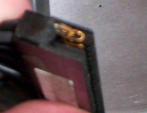
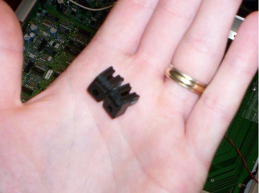
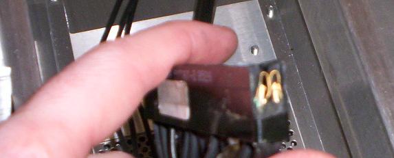
I stripped the PJ right down to the chassis and began the arduous task of cleaning each contact with compressed air and contact cleaner. I get to the LVPS chassis connector and ( for the first time ) I notice that there is some silastic on the plastic part of the connector. Looking at it front on, it looks no different to the HVPS connector, but, with the tubes removed and chassis fan assembly taken away - it was easy to see
The damn thing had been broken! 
At some stage in the past, someone has upgraded both P/S's and when they have remounted them, they have forced the LVPS in against its wishes and - - - -SNAP!
Both mounts on either side snapped clean off and the connector retreated into the chassis.
When repairs were done - they used a soft rubber silastic. Whilst this wouldn't have been my choice, it did the job temporarily. When I sent my LVPS to Curt to get my heater filament voltage mod done, and then replaced it - Boom, the silastic gave way again.
Attached are some photos.
Have repaired with Epoxy and am waiting 24 hours for that to set before testing it out. Then I can try my new moome HDMI card and my new astig components. JOY.
| Description: |
|
| Filesize: |
18.44 KB |
| Viewed: |
8970 Time(s) |
|
| Description: |
|
| Filesize: |
23.63 KB |
| Viewed: |
8970 Time(s) |
|
| Description: |
|
| Filesize: |
17.28 KB |
| Viewed: |
8970 Time(s) |
|
|
|
| Back to top |
|
|
Tim in Phoenix
Joined: 21 Oct 2006
Posts: 4409
Location: Phoenix
|
| Posted: Sun Aug 19, 2007 4:55 pm Post subject: |
|
|
Wow
That would have taken some force! I have seen also where some of the contacts in the connector body had not been snapped into place and the voltage on those teeth would intermit.
|
|
| Back to top |
|
|
tse
Joined: 03 May 2006
Posts: 1014
Location: Sweatbucket, Fl.
|
| Posted: Sun Aug 19, 2007 5:09 pm Post subject: |
|
|
Would you believe that the date on the manufacturers drawing for that connector is 1962? It isn't the easiest thing in the world to find anymore.
Scott
_________________
"Were we directed from Washington when to sow and when to reap, we would soon want bread."
Thomas Jefferson
|
|
| Back to top |
|
|
PJMoore
Joined: 05 Oct 2006
Posts: 99
|
| Posted: Sun Aug 19, 2007 11:34 pm Post subject: |
|
|
One of the two mounting tabs on the black bulkhead connector for my LVPS is also broken. I suspect the best way to deal with this is to epoxy it. Does anyone know if this part is actually available anymore?
I am beginning to wonder if my intermittent "blanking" and/or image rip (as if it lost sync) is attributable to this connector.
|
|
| Back to top |
|
|
Tim in Phoenix
Joined: 21 Oct 2006
Posts: 4409
Location: Phoenix
|
| Posted: Mon Aug 20, 2007 12:19 am Post subject: |
|
|
| PJMoore wrote: | One of the two mounting tabs on the black bulkhead connector for my LVPS is also broken. I suspect the best way to deal with this is to epoxy it. Does anyone know if this part is actually available anymore?
I am beginning to wonder if my intermittent "blanking" and/or image rip (as if it lost sync) is attributable to this connector. |
You could as easily swap out the entire internal harness set with one from a partsd frame, Curt might be able to get you one.
|
|
| Back to top |
|
|
Curt Palme
CRT Tech
Joined: 08 Mar 2006
Posts: 24396
Location: Langley, BC
TV/Projector: All of them!
|
| Posted: Mon Aug 20, 2007 1:52 am Post subject: |
|
|
Funny, two requests in 24 hours for these connectors.. I think I have ONE right now, I've never saved them. I think I have ONE right now, I've never saved them.
1962 vintage for the connector? Now THAT'S stable technology..
|
|
| Back to top |
|
|
listenlounge
Joined: 29 Apr 2007
Posts: 48
Location: NSW, Australia
|
| Posted: Mon Aug 20, 2007 2:06 am Post subject: |
|
|
Indeed he does - Curt has one spare if you want to replace the whole harness. PM or email him.
If you want to attempt the repair, it is fairly simple.
You will need a toothpick, a good quality 2 part epoxy and a clamp of some sort
First, remove the tube assemblies, then the aluminium base plate ( with the 3 foam rests on it ) by removing the four screws, and then the fan bay just lifts out. This gives you access to the harness at the rear of the connector.
Remove your remaining good screw from the connector and CAREFULLY push the connector forward into the PS bay.
Make sure you don't strip the insulation to any of the wires on the sharp edge!
Use the toothpick to apply the epoxy. Clamp it and leave overnight - be careful not to get any epoxy in the groove that guides the PCB into to connector, or on the contacts themselves.
Wait overnight, then reassemble. I suggest replacing the P/S's FIRST, so that you can guide them in from the top and ensure that they mate correctly and firmly ( Oooh - that sounded rude )
Then you reassemble the rest!
Take some pics - it may help someone else, and I was too lazy to document the repair....
Cheers
Ben
|
|
| Back to top |
|
|
|
|


