| Author |
Message |
fragzero
Joined: 30 Aug 2012
Posts: 344
|
| Posted: Wed Jan 09, 2013 1:23 pm Post subject: 808s setup questions |
|
|
Yesterday i spend some time with my 808.
Setup
Cine 8 boards
DVB180 tubes (face looks perfect - 800 hours)
BD808s RGB amps (75mhz)
scheimpflug mounts
VP50 pro + HDFury III
1440x960P 60 and 72hz
90inch 16:9 1.2gain screen
I used the Barco Setup Quick reference guide but having some issues with the setup.
(1a) Check the 48V pot on the SMPS (see service manual).
where can i find this? everyone keeps talking about the potentiometer but i can't locate it. This controls horizontal width if i'm correct? Currently at 85-87 / 100 on horizontal width.
(1b) Check the horizontal linearity pot on the horizontal deflection board (see service manual).
I found this meter, Seems Kal used this to get rid of the left side banding but this does not work for me, turning the potentiometer influences the width of the image and banding reduces a little bit but it's still visible on the left.
(4) Raster width coils: Turn all 3 all the way in. Adjust the two larger rasters to match the smallest in width at the center point. (Use the horizontal R/B shift pots to make it easier to line things up and measure the left to right horizontal centerline). One of the 3 coils must be turned all the way in! Note: Do not use a metallic screwdriver to adjust these coils. You'll fry the coil and possibly the surrounding area.
How important is this? I do not have any tools to adjust these coils so i just left them alone (coils and tubes are not a factory matched set).
some issues i have after the first pass
1)i can't get convergence 100% on the left side of the image. Either the most left part is converged and near 1/4th of the image is a little off or the other way around. Probably due to a setup issue.
2) The vertical banding on the left side, i can add back porch and move the image but what does this actually mean for the electronics? Will this increase bandwith? (since these are hidden pixels). Haven't noticed it yet outside of test patters, is it better to live with this?
It's far from perfect currently but i can seen scanlines at 960P, i do think they are touching but certainly not at 720p or 768p. Is 960P a good idea with my setup? Probably upgrading to 120mhz amps in the future.
|
|
| Back to top |
|
 |
Ile
Joined: 09 Mar 2006
Posts: 1491
Location: Jyväskylä, Finland
|
| Posted: Thu Jan 10, 2013 9:24 am Post subject: Re: 808s setup questions |
|
|
| fragzero wrote: | (1a) Check the 48V pot on the SMPS (see service manual).
where can i find this? everyone keeps talking about the potentiometer but i can't locate it. This controls horizontal width if i'm correct? Currently at 85-87 / 100 on horizontal width.
|
Leave it alone, it's fine now.
That voltage measurement is useless, because it chances with horizontal freq you will use. 48V is universal factory adjustment with 15kHz freq, nobody use that small resolutions these days. If you use this method, you probably don't get wide enough raster for 1080i/p, because when SM was written 1920x1080 was not invented yet.  I guess something like 1600 horizontal pixels was highest resolution from computer back then. I guess something like 1600 horizontal pixels was highest resolution from computer back then.
Better method is using highest resolution you will use and then set 95 from menu. Then adjust pot from smps daughter board.
| fragzero wrote: | (1b) Check the horizontal linearity pot on the horizontal deflection board (see service manual).
I found this meter, Seems Kal used this to get rid of the left side banding but this does not work for me, turning the potentiometer influences the width of the image and banding reduces a little bit but it's still visible on the left. |
It's meant to use for linearity adjustment with 18kHz signal.
| fragzero wrote: | (4) Raster width coils: Turn all 3 all the way in. Adjust the two larger rasters to match the smallest in width at the center point. (Use the horizontal R/B shift pots to make it easier to line things up and measure the left to right horizontal centerline). One of the 3 coils must be turned all the way in! Note: Do not use a metallic screwdriver to adjust these coils. You'll fry the coil and possibly the surrounding area.
How important is this? I do not have any tools to adjust these coils so i just left them alone (coils and tubes are not a factory matched set). |
It's needed if rasters aren't about same sized when convergence are nulled.
I use sharpened wooden chopstick for adjustment (tip is now like screwdriver).
| fragzero wrote: | (1)i can't get convergence 100% on the left side of the image. Either the most left part is converged and near 1/4th of the image is a little off or the other way around. Probably due to a setup issue.
2) The vertical banding on the left side, i can add back porch and move the image but what does this actually mean for the electronics? Will this increase bandwith? (since these are hidden pixels). Haven't noticed it yet outside of test patters, is it better to live with this?
It's far from perfect currently but i can seen scanlines at 960P, i do think they are touching but certainly not at 720p or 768p. Is 960P a good idea with my setup? Probably upgrading to 120mhz amps in the future. |
Bigger porch should help also for left side convergence. Yes, bigger porch means more pixels to horizontal scan, so it have higher horizontal freq that also elevates BW requirements.
There's no idea to use 960p, because there is no content with that resolution. Use 720p or 1080i depending of content. Smaller resolution also means smaller stress -> smaller noise level to theater. If you really get that sharp picture with 720p that scanlines bothers from seating position, then something higher would be useful.
Many scaler users cut black borders from picture with scaler and use something like 1920x800p, actual vertical count depend about movies AR. Can that be done with VP-50 pro? It makes sense to leave black borders out from stressing projector.
|
|
| Back to top |
|
|
Hulio
Joined: 15 Apr 2006
Posts: 494
Location: Belgium
|
| Posted: Thu Jan 10, 2013 10:16 am Post subject: |
|
|
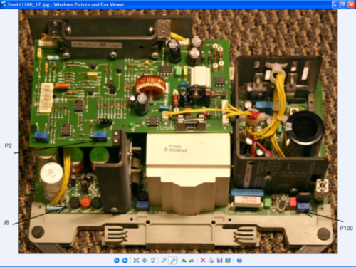
In case you did not checked the 17V rail already, do it first. Display a picture at standard frequency ( S-video on port 2 ) or internal generated testpattern at 15,6 Khz and put the contrast and brightness at 49. Turn P100 pot on the SMPS for a +17,2V reading at J8 testpoint.
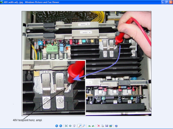
Now, the 48V. With the same picture and settings, put the horizontal width at max. ( 99 ). Adjust the P2 pot on the SMPS sub-board for a +48V reading at the collector of Q3 transistor on the horizontal deflection board ( second board on the leftside, facing the back of the projector ).
You should have a steady hand and gently put your probe on the mounting base of the transistor, like in the picture. ( no need looking for the middle leg of the transistor, this is connected with the mounting base ). Touching the metal clip or something else will short the tranny.
Good luck and let us know.
| Description: |
|
| Filesize: |
385.93 KB |
| Viewed: |
6535 Time(s) |
|
| Description: |
|
| Filesize: |
405 KB |
| Viewed: |
6535 Time(s) |
|
|
|
| Back to top |
|
|
fragzero
Joined: 30 Aug 2012
Posts: 344
|
| Posted: Thu Jan 10, 2013 11:25 am Post subject: |
|
|
I have the 17volt point at 17.01volts? Isn't that whats needed?
Thanks for the information about the 48v point!
@960p Well the desktop is sharper at 960P compared to 720P (my HTPC is feeding 1080p24). Since i also watch 1080p material (htpc xbox bluray) i'd like to configure 960p. 1080i is nice but the scanlines are a bit annoying at 1080i.
Played with the focus coils + optical focus yesterday from what i can see the scanlines are touching, if i push resolution up any more i will certainly have overlap.
I suppose this is great for these tubes? Astig adjustments have been done in the past for a screen size similar to mine. I adjusted the focus coils and optical focus, will do zone focus tonight.
When watching 2.35:1 or 2.4:1 content i could change my resolution to 1920x800 and zoom vertical so the entire visible image is 800px (or 817).
|
|
| Back to top |
|
|
Ile
Joined: 09 Mar 2006
Posts: 1491
Location: Jyväskylä, Finland
|
| Posted: Fri Jan 11, 2013 7:50 am Post subject: |
|
|
| fragzero wrote: | | I have the 17volt point at 17.01volts? Isn't that whats needed? |
This is ok for 808.
| fragzero wrote: | | 1080i is nice but the scanlines are a bit annoying at 1080i. |
Have you tested 1080i96Hz it flicker less than 60Hz or 72Hz. With desktop you still can see some flickering, but with video it's fine for me.
Much sharper than scaling it down to 960.
|
|
| Back to top |
|
|
fragzero
Joined: 30 Aug 2012
Posts: 344
|
| Posted: Fri Jan 11, 2013 9:58 am Post subject: |
|
|
| Quote: | | Have you tested 1080i96Hz it flicker less than 60Hz or 72Hz. With desktop you still can see some flickering, but with video it's fine for me. |
Watched Kill Bill 1 in 1080p yesterday, since you suggested it i tried 1080p24 -> 1080i72, desktop was flickering but never saw it during the movie. Image was sharper!
So will swap from 960p to 1080i!
Another small question, before i had G2 a bit too high, yesterday i adjusted G2 until barely visible.
Before adjusting G2 i added gamma boost with a RTC2200, details in dark were very visible, i was able to lower contrast and brightness and the image was very enjoyable. (best i have ever had)
Now after adjusting G2 i lost most of the details in dark again.
One thing i can think of is that my G2 is too low (brightness 50 - contrast 1, raster barely visible)
The other reason is my room, i have white walls and ceiling and a white-grayish floor. Could this result in the need for more G2 (this influences the point at which the tubes start shinning right?).
I could turn G2 up now - is there any disadvantage in doing so? I could probably lower brightness and contrast again (currently 50 and 75).
|
|
| Back to top |
|
|
fragzero
Joined: 30 Aug 2012
Posts: 344
|
| Posted: Sat Jan 19, 2013 1:18 pm Post subject: |
|
|
So i got a little further with my setup but having an issues with the horizontal lines.
After a reset of all settings and displaying a pattern with horizontal lines i have the following image. ( This is an exaggeration)

And rotating the focus yokes seems to change the curving of the image. Depending on how i rotate the yokes i can almost get the lines straight.
Is this normal? I can compensate this with convergence but it feels like I'm doing something wrong, and if i am i'm overusing convergence = increasing drift possibility.
Another thing, i adjusted the Raster width coils this morning, seems this affected my geometry ( i turned down green by quite a bit).
After resetting all settings and doing mechanical/electrical adjustments i have the following image (feeding a full green screen). again,this is an exaggeration

To get the sides straight i have to use the side bow + keystone to get the right side parallel to the projection screen.
Afterwards i use the left side adjustments to get the left side parallel. I can't get the left side 100% parallel, i always end up with a small gap at the bottom left side.
What can i do about this? Left keystone is at 0/100 and it's still not enough. Am i doing something really wrong? Some mechanical or electrical error?
|
|
| Back to top |
|
|
Ile
Joined: 09 Mar 2006
Posts: 1491
Location: Jyväskylä, Finland
|
| Posted: Mon Jan 21, 2013 10:02 am Post subject: |
|
|
G2 is probably fine and you can use brightness to final adjustment.
Do you have any test picture for adjusting brightness?
You need some "pluge pattern" for that. Some BR test disc would be best, so you can be sure that all your pc settings are fine.
Here's info for brightness adjustment
http://www.curtpalme.com/forum/viewtopic.php?p=115921#115921
Not so sure if turning focus yokes is that good method for adjusting bow. When it's turned, I'd guess that focus areas aren't where those supposed to be.
Have you tested to turn green deflection yoke little cw, maybe then left edge adjustment have enough range to fix corner.
|
|
| Back to top |
|
|
fragzero
Joined: 30 Aug 2012
Posts: 344
|
| Posted: Mon Jan 21, 2013 10:23 am Post subject: |
|
|
I turned G2 up a little bit and i have all detail back, very small difference. Probably okay like this!
Yesterday i checked the focus coil and noticed i had a KF-3205 on my green tube instead of a KF-3205G (all original barco parts, serial numbers matched). I transferred a KF-3205G from my spare BD808s just to be sure. I also adjusted the yoke and played with horizontal skew. got everything aligned! Seems horizontal skew was the solution.
I should tape some wires to my screen to check geometry in all directions!
Now about the focus coils, what's the normal position? Those coils can rotate freely so how do i know where they have to go?Currently i have them with the connector to the opening.
Seems i also have some left side convergence issues.

Anything i can do about this?
|
|
| Back to top |
|
|
Ile
Joined: 09 Mar 2006
Posts: 1491
Location: Jyväskylä, Finland
|
| Posted: Mon Jan 21, 2013 11:04 am Post subject: |
|
|
| fragzero wrote: | | Now about the focus coils, what's the normal position? Those coils can rotate freely so how do i know where they have to go?Currently i have them with the connector to the opening. |
Connectors up to opening and connector plane about level.
| fragzero wrote: | | Anything i can do about this? |
I would try narrower red raster from width coil or wider green. Coils usually affect also to horizontal linearity so something should happen.
|
|
| Back to top |
|
|
fragzero
Joined: 30 Aug 2012
Posts: 344
|
| Posted: Mon Jan 21, 2013 11:16 am Post subject: |
|
|
I already adjusted the coils last week. What i did:
- reset all settings
- used the potentiometers to align all the colors
- Turned all down
- adjusted 2 coils so they all were the same width
and then returned to potentiometers to their default positions and readjusted everything.
I'll try increasing green.
|
|
| Back to top |
|
|
|
|


