| Author |
Message |
ronaldus
Joined: 25 Dec 2010
Posts: 183
Location: france
|
| Posted: Thu Apr 26, 2012 8:57 pm Post subject: VNB upgrade question |
|
|
Hi everybody,
I'm trying to upgrade my 9500LC neckboards.
For the moment I've just changed the two capacitors C1 and C26 (original 22uf 100V replaced by 33uF 180V).
After I installed the VNB back in the projector I switched on the projector and I heard a loud tick (like an arc).
Strange thing is that it seemed to happen before the HV came in (not 100% sure). The projector fired up normally and the tube that I worked on (blue) worked normally. I switched the projector off with the remote and the unplugged it and took the VNB out to see if I could see something. All OK.
The only thing I didn't connect was the ground strip that normally goes from the VNB shielding to the big heatsink in the back of the projector.
Could that be the cause? Normally I allways have those strips connected.
For the time being I'm not very lucky with my mods
Could anybody shine a light on this?
Regards,
Ron.
|
|
| Back to top |
|
 |
Nashou66

Joined: 12 Jan 2007
Posts: 16171
Location: West Seneca NY
|
|
| Back to top |
|
|
draganm
Joined: 08 Mar 2006
Posts: 8990
Location: Colorado
|
| Posted: Thu Apr 26, 2012 10:22 pm Post subject: |
|
|
| Nashou66 wrote: | Yes if those ground straps are not connected the static charge built up on the tube has no where to drain to.
Athanasios |
yup.
The tube bell can build up a big charge. It's shuttled back to the VNB's through the 2 big Black wires, then to the sheet-metal bridge on top of the card and the spark arrestors under them, the cards ground plane, then the card cage, and ultimately the rear heat-sink 
22 Uf is the ideal value back there but the 180VDC rating is the important part. Use the highest quality capacitor here you can find with low ESR to filter AC noise.
Next big noise issue is the P14 line jumping over the primary video processor
|
|
| Back to top |
|
|
Nashou66
Joined: 12 Jan 2007
Posts: 16171
Location: West Seneca NY
|
| Posted: Thu Apr 26, 2012 11:02 pm Post subject: |
|
|
| draganm wrote: | | Nashou66 wrote: | Yes if those ground straps are not connected the static charge built up on the tube has no where to drain to.
Athanasios |
yup.
The tube bell can build up a big charge. It's shuttled back to the VNB's through the 2 big Black wires, then to the sheet-metal bridge on top of the card and the spark arrestors under them, the cards ground plane, then the card cage, and ultimately the rear heat-sink
22 Uf is the ideal value back there but the 180VDC rating is the important part. Use the highest quality capacitor here you can find with low ESR to filter AC noise.
Next big noise issue is the P14 line jumping over the primary video processor |
I jumped to 100uf 160VDC Panasonic's.  They work really well there. The card cage just barely fits over them They work really well there. The card cage just barely fits over them 
Nashou
_________________
Don't blame your underwear for your crooked ass~ unknown Greek philosopher
"Republicans believe every day is the Fourth of July, but the Democrats believe every day is April 15." --- President Reagan
One Smart Dog!!!
Marquee High Performance Bellows now shipping!!
Marquee Modifications and Performance Enhancement
Marquee C-element and Bellow removal
|
|
| Back to top |
|
|
ronaldus
Joined: 25 Dec 2010
Posts: 183
Location: france
|
| Posted: Fri Apr 27, 2012 7:27 am Post subject: |
|
|
Hy everybody,
This is what I've put in:
http://www2.mouser.com/Search/Refine.aspx?Keyword=66+7eca+2chg330&OrgTerm=66-7eca-2chg330&NewSearch=1
They are 160V instead of 180V. I guess i need new glasses 
I guess I can continue with the carbon resistor changes. I've followed your recommendations Nashou and bought 2Watt ohmites. but they seem to be quite big. I hope they will fit in.
I also have a replacement for the HF1100 that's on my VNB's
For the VNB's I find i tricky to go with small steps because this means a lot of mounting and unmounting and i find the tube pins very fragile.
Anyway I'm glad i did with this first VNB. Maybe I can do the other VNB's in two steps; resitors plus caps then the chips?
Cheers,
Ron.
|
|
| Back to top |
|
|
ronaldus
Joined: 25 Dec 2010
Posts: 183
Location: france
|
| Posted: Sun Apr 29, 2012 11:55 am Post subject: |
|
|
Hi it's me again,
I just discovered that the H convergence doesn't work anymore. I guess that spark hit something else then only the back heatsink )-:
If I move the H convergence it hardly moves but I see the green decreasing! All cables should be good because I didn't move them.
I now rember the the earth strip of the red VNB case was dangling in the projector when i switched it on.
Stupid beginners mistake!!
I hope i can repaire it.
Cheers,
Ron.
|
|
| Back to top |
|
|
draganm
Joined: 08 Mar 2006
Posts: 8990
Location: Colorado
|
| Posted: Sun Apr 29, 2012 5:14 pm Post subject: |
|
|
| ronaldus wrote: | Hi it's me again,
If I move the H convergence it hardly moves but I see the green decreasing! All cables should be good because I didn't move them.Ron. |
what doesn't move, the center zone or the outer zones? On the outer zones there is vertical and horizontal , each color has it's own channel and is made up of 4 small amps in a push-pull configuration if I remember correctly. Check the big FET's clipped to the sink and the small dipped ceramics
|
|
| Back to top |
|
|
ronaldus
Joined: 25 Dec 2010
Posts: 183
Location: france
|
| Posted: Sun Apr 29, 2012 5:20 pm Post subject: |
|
|
Hi,
Yes it's in the outer region. I've swapped with the blue tube and then it works so it's on the amplifier but it could off course come from the CLM since the green moves when I move the red (some crosstalk because of broken dac or opamp?) I'll check if i take teh two 24v jumpers out and see if the green still moves. If that's the case then I guess it comes from before the amp.
Cheers,
Ron.
|
|
| Back to top |
|
|
ronaldus
Joined: 25 Dec 2010
Posts: 183
Location: france
|
| Posted: Tue May 01, 2012 9:46 pm Post subject: |
|
|
Hi Everybody,
I've found the problem.
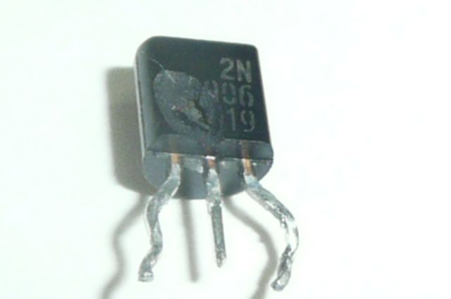
Q226 had blown up (I forms a constant current source for the push pull amplifier. I've replaced it by a general purpose PNP transistro (BC559) ant it works again.
I would have never thought that this sparks vould do such a damage.
I'm i happy man again:-)
I've attached a picture of the transistor.
| Description: |
|
| Filesize: |
17.55 KB |
| Viewed: |
8454 Time(s) |
|
|
|
| Back to top |
|
|
Nashou66
Joined: 12 Jan 2007
Posts: 16171
Location: West Seneca NY
|
| Posted: Tue May 01, 2012 10:01 pm Post subject: |
|
|
| ronaldus wrote: | Hi Everybody,
I've found the problem.
Q226 had blown up (I forms a constant current source for the push pull amplifier. I've replaced it by a general purpose PNP transistro (BC559) ant it works again.
I would have never thought that this sparks vould do such a damage.
I'm i happy man again:-)
I've attached a picture of the transistor. |
Is that the transistor on the daughter board for the HDM?
Athanasios
_________________
Don't blame your underwear for your crooked ass~ unknown Greek philosopher
"Republicans believe every day is the Fourth of July, but the Democrats believe every day is April 15." --- President Reagan
One Smart Dog!!!
Marquee High Performance Bellows now shipping!!
Marquee Modifications and Performance Enhancement
Marquee C-element and Bellow removal
|
|
| Back to top |
|
|
ronaldus
Joined: 25 Dec 2010
Posts: 183
Location: france
|
| Posted: Wed May 02, 2012 5:41 am Post subject: |
|
|
Hi Athanasios,
The transistor is on the convergence amplifier and in this case it was on the RED horizontal channel.
To check that it was not on the CLM I tied the two control signals for H green and red together and when i did a convergence on red i saw the green moving so the control was working. Also the skew didn't work on red and that uses the same amplifier so that's another proof that the problem was on the amplifier.
The broken transistor behaved as an open circuit. So by measuring the voltage drop over base emitter i discovered that this one was broken.
I'll continue the upgrade of my other two neck boards.
I didn't see a lot of improvement but I only did the blue VNB.
I'll swap it with the green to see if it really makes a difference
Ron
|
|
| Back to top |
|
|
ronaldus
Joined: 25 Dec 2010
Posts: 183
Location: france
|
| Posted: Wed May 02, 2012 10:15 pm Post subject: |
|
|
Hi,
me again.
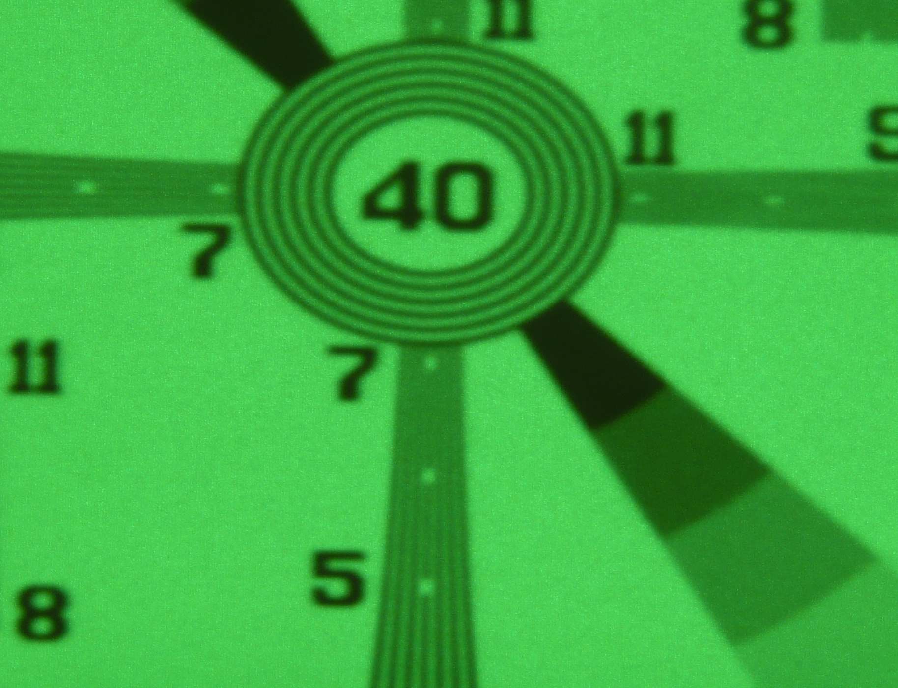
I've done a small test before after with only the two Electrolytic caps and 4 carbon resistors changed.
I was asthonished that there was a substantial difference after only the small changes.
I'll repeat this test when I have also changed the HF1100 chip.
Test was done in the center of the screen with a 1080P test pattern.
Photo taken with panasonic lumix on tripod with long exposure night mode.
I've added the same screenshot with also the chip changed.
I think with the old chip its better!
| Description: |
|
| Filesize: |
191.84 KB |
| Viewed: |
6463 Time(s) |
|
| Description: |
|

Download |
| Filename: |
VNB afterMod+chip.jpg |
| Filesize: |
366.49 KB |
| Downloaded: |
392 Time(s) |
| Description: |
|
Download |
| Filename: |
VNB afterMod.jpg |
| Filesize: |
180.64 KB |
| Downloaded: |
422 Time(s) |
Last edited by ronaldus on Thu May 03, 2012 11:33 pm; edited 2 times in total
|
|
| Back to top |
|
|
Nashou66
Joined: 12 Jan 2007
Posts: 16171
Location: West Seneca NY
|
|
| Back to top |
|
|
ronaldus
Joined: 25 Dec 2010
Posts: 183
Location: france
|
| Posted: Sun May 06, 2012 5:04 pm Post subject: |
|
|
Hi again,
I would like to compare the performance of my VNB with yours.
Could anybody try to show my test pattern on their projector and take a screen shot like i published in this thread?
Off course It'll test the whole signal path and not the VNB only but it would be nice to check it and it should not take much time.
for what i see now I can not resolve 1080p at all and I don't see scan lines at 1080p and 720p
My screen size is 2.4 meters wide.
I still have to do the Focus board mod.
It will be highly appreciated!
regards,
Ron.
| Description: |
|
Download |
| Filename: |
1080p testpattern.jpg |
| Filesize: |
420.89 KB |
| Downloaded: |
394 Time(s) |
|
|
| Back to top |
|
|
stridsvognen
Guest
|
| Posted: Sun May 06, 2012 5:50 pm Post subject: |
|
|
Hi Ron.
I just put up your test pattern, but directly out of my laptop 1080i to my VP50, and 1080P 72hz out from vp50 it only filled out 3/4 of the screen, this is how looks here with standard VNB
Should do better if i can put it up in native resolution. full screen.
|
|
| Back to top |
|
|
ronaldus
Joined: 25 Dec 2010
Posts: 183
Location: france
|
| Posted: Sun May 06, 2012 6:39 pm Post subject: |
|
|
Thanks Stridsvognen,
I'm looking forward to see the picture with the filled screen!
I'm running my projector at 60 hz
I've checked the image and it's 1924x1088 pixels
Cheers,
Ron.
|
|
| Back to top |
|
|
stridsvognen
Guest
|
| Posted: Sun May 06, 2012 7:05 pm Post subject: |
|
|
I just made the pics.. wait 15 min, my camera just need to charge a little before i can transfer the pics-
Kurt
|
|
| Back to top |
|
|
stridsvognen
Guest
|
| Posted: Sun May 06, 2012 7:18 pm Post subject: |
|
|
|
Here you go.... The best i can do.
|
|
| Back to top |
|
|
ronaldus
Joined: 25 Dec 2010
Posts: 183
Location: france
|
| Posted: Sun May 06, 2012 7:28 pm Post subject: |
|
|
Thank you very much!
I see that I'm not quite at your level.
I'll come back when I've done some upgrade to my focus board.
Cheers,
Ron.
|
|
| Back to top |
|
|
Nashou66
Joined: 12 Jan 2007
Posts: 16171
Location: West Seneca NY
|
|
| Back to top |
|
|
|
|


