| Author |
Message |
cmjohnson

Joined: 03 Apr 2006
Posts: 5180
Location: Buried under G90s
|
| Posted: Sat Jul 02, 2016 9:57 pm Post subject: |
|
|
I'm looking into the possibility of making a 12 channel bipolar power supply assembly that would drive the G90 4/6 pole CPC rings.
The parts are cheap, and there's nothing tough about the circuit. It's just a variable bipolar +/-6v supply, 1/2 amp per channel, and you'd need 12 of them. With 12 trim pots for control, and build it to fit in the slot where you'd put your quad decoder board, since I think most people don't use those.
|
|
| Back to top |
|
 |
cmjohnson
Joined: 03 Apr 2006
Posts: 5180
Location: Buried under G90s
|
| Posted: Mon Jul 04, 2016 1:12 pm Post subject: |
|
|
In a word, yes, it is feasible for me to make a driver board to drive the G90's electronic CPC ring sets from a Marquee.
Or, actually, from any projector. The main board itself will be small enough that it can fit into a spare card slot space in any
projector, but it will require connection to a suitably robust DC power source or the addition of a separate power supply to feed it,
plus provisions have to be made to route all the required cables.
The PC board house will be providing me with several boards in the initial order and I plan to build them all out, and test them,
of course. So I should have extras to sell if anybody else wants to try running G90 CPC ring sets in any other projector.
|
|
| Back to top |
|
|
CIR Engineering

Joined: 25 Aug 2008
Posts: 4269
Location: Chicago USA & Berlin Germany
|
| Posted: Mon Jul 04, 2016 5:29 pm Post subject: |
|
|
| cmjohnson wrote: | However, for test purposes, we COULD "borrow" the astig circuit from red or blue and use it to drive the 6 pole circuit, while using the astig from green to drive the 4 pole circuit, which would leave one CRT without astig control of any kind.
So think about that: Green has 4 pole astig, and uses blue's astig circuit to drive the 6 pole astig winding. Red uses its own 4 pole astig circuit, blue, which has the LEAST effect on picture sharpness, runs without electronic astig.
I'll be trying that. |
I like this idea a lot. You could do the best job possible with mechanical astig on the blue and then run the 6-poles on the red and green... done! (hopefully)
The best part is that you can do the 4 and 6-pole astig at the screen instead of all the way back at the projector. You will have true remote controlled astig for 4 and 6-pole at all zones which I think is a huge advantage on the G90. It's a lot easier to see astig when you are two feet from the scren as opposed to 13 feet.
I can't wait to see how this comes out!
craigr
_________________
JETI 1501-HiRes 2nm Spectroradiometer
JETI 1211 Spectroradiometer
Photo Research PR-650 Spectroradiometer
Klein K10-A Colorimeter
Murideo Fresco SIX-G HDMI 2.x Multimedia Generator
Murideo Fresco SIX-A HDMI 2.x Analyzer
Light Illusion ColourSpace XPT Color Calibration Software
Light Illusion LightSpace XPT Pro Version 10.x Color Calibration Software
OMARDRIS JVC Software Patch to use K10-A and Jeti with JVC OEM AutoCal Software!
Sencore CR7000 CRT Tube Analyzer / Rejuvenater
Authorized Dealer for Lumagen & just about everything worth buying 
www.CIR-Engineering.com - craigr@cir-engineering.com
Phone: 865-405-6892
|
|
| Back to top |
|
|
cmjohnson
Joined: 03 Apr 2006
Posts: 5180
Location: Buried under G90s
|
| Posted: Mon Jul 04, 2016 6:57 pm Post subject: |
|
|
To contribute yet another level of nuttiness to this idea, it had occurred to me that it may be possible to wire up a second astig system using spare Marquee parts and a separate I2C bus controller. Use an Atmel controller to create a limited system where the only thing the second controller can control would be another astig system. Slave it into the chassis and have something truly bizarre and unique.
I know it's too big a project for me to handle by myself. But it's certainly possible for someone who is a higher level engineer than I am.
|
|
| Back to top |
|
|
gregstv
Joined: 27 Aug 2007
Posts: 628
Location: Australia
|
| Posted: Mon Jul 04, 2016 7:56 pm Post subject: |
|
|
| cmjohnson wrote: | To contribute yet another level of nuttiness to this idea, it had occurred to me that it may be possible to wire up a second astig system using spare Marquee parts and a separate I2C bus controller. Use an Atmel controller to create a limited system where the only thing the second controller can control would be another astig system. Slave it into the chassis and have something truly bizarre and unique.
I know it's too big a project for me to handle by myself. But it's certainly possible for someone who is a higher level engineer than I am. |
Keep at it. Its not about the level of Engineer, its about learning as you go. Remember the goal is to learn something new everyday which is what you are doing.
I have been modding my Barco 919 for quite some time. Mainly reducing noise. There is great satisfaction when you see improvement from what you have tried. The anticlimax is that there are very few people interested in what we have achieved with CRT projector mods. I am still enjoying it and having fun just like yourself.
I am contemplating fitting LUGs to the XG I have sitting under the house as my next project.
|
|
| Back to top |
|
|
barclay66

Joined: 27 Jun 2011
Posts: 1304
Location: Germany
TV/Projector: Marquee 9500 Ultra
|
|
| Back to top |
|
|
cmjohnson
Joined: 03 Apr 2006
Posts: 5180
Location: Buried under G90s
|
| Posted: Mon Jul 04, 2016 9:23 pm Post subject: |
|
|
Neat! And here I was, just starting to wonder if there might be a control pathway that I could use.
But is it enough? Every astig circuit needs two control channels. N/S and E/W.
We're still short by three control paths.
It'd be so much easier if the CLM was easily hackable. But it's anything but that. Its firmware is stored in write-once proms.
And the development system runs on old Sun hardware. VDC may be in posession of the only CLM development system in the world, and I'll bet it hasn't been turned on in five years or more.
And who even would know how to develop anything on it?
At this point in the game it would probably be easier to develop a brand new CLM based on some modern FPGA.
|
|
| Back to top |
|
|
gjaky
Joined: 05 Jun 2010
Posts: 2802
Location: Budapest, Hungary
|
| Posted: Tue Jul 05, 2016 5:37 am Post subject: |
|
|
If you are really into this why not look up some genuine Electrohome engineer, maybe they are willing to help...
Hint: Barclay66 found a list of person in one of the EPROMs who supposedly made the Marquee. For example the video schematics (VIM, VNB) are mostly signed by "MP" -no not Mike Parker, but if you look up Barclay's list you find Mike Pfeifle as a good match, now if you look up his linked-in profile you find he is still working foe Christie digital (and was a former EH worker), so you only need the lead and maybe it will get to the person who know the most about the board you are interested.
_________________
projectors in the past : NEC 6-9PG xtra, Electrohome Marquee 6-7500, NEC XG 1351 LC ( with super modified Electrohome VNB neckboard !!!)
current: VDC Marquee 9500LC
The MOD: VNB-DB, VIM-DB
|
|
| Back to top |
|
|
cmjohnson
Joined: 03 Apr 2006
Posts: 5180
Location: Buried under G90s
|
| Posted: Tue Jul 05, 2016 11:11 pm Post subject: |
|
|
Going back to the subject of running G90 yokes on a Marquee, I've found them to be excellent when they're behind a G90 deflection yoke.
The problem is that the G90 deflection yoke is not very compatible with a Marquee without some modifications to the yoke, the HDM, or both.
The raster is simply WAY too wide and if the yoke is connected to the green channel, you get no picture because the current sense circuit on the HDM senses too much current draw. Interestingly, only the green channel has the current sense circuit. So I have been able to run a G90 yoke on the red and blue channels.
The raster can't be brought down to within the CRT face area even with H. size at zero.
I'm looking at ways to reduce the overall drive level of the HDM. It's not as easy to do this as I might have hoped.
|
|
| Back to top |
|
|
CIR Engineering
Joined: 25 Aug 2008
Posts: 4269
Location: Chicago USA & Berlin Germany
|
| Posted: Tue Jul 05, 2016 11:50 pm Post subject: |
|
|
| cmjohnson wrote: | Going back to the subject of running G90 yokes on a Marquee, I've found them to be excellent when they're behind a G90 deflection yoke.
The problem is that the G90 deflection yoke is not very compatible with a Marquee without some modifications to the yoke, the HDM, or both.
The raster is simply WAY too wide and if the yoke is connected to the green channel, you get no picture because the current sense circuit on the HDM senses too much current draw. Interestingly, only the green channel has the current sense circuit. So I have been able to run a G90 yoke on the red and blue channels.
The raster can't be brought down to within the CRT face area even with H. size at zero.
I'm looking at ways to reduce the overall drive level of the HDM. It's not as easy to do this as I might have hoped. |
I assume you have adjusted the magnets on the HDM right?
craigr
_________________
JETI 1501-HiRes 2nm Spectroradiometer
JETI 1211 Spectroradiometer
Photo Research PR-650 Spectroradiometer
Klein K10-A Colorimeter
Murideo Fresco SIX-G HDMI 2.x Multimedia Generator
Murideo Fresco SIX-A HDMI 2.x Analyzer
Light Illusion ColourSpace XPT Color Calibration Software
Light Illusion LightSpace XPT Pro Version 10.x Color Calibration Software
OMARDRIS JVC Software Patch to use K10-A and Jeti with JVC OEM AutoCal Software!
Sencore CR7000 CRT Tube Analyzer / Rejuvenater
Authorized Dealer for Lumagen & just about everything worth buying
www.CIR-Engineering.com - craigr@cir-engineering.com
Phone: 865-405-6892
|
|
| Back to top |
|
|
cmjohnson
Joined: 03 Apr 2006
Posts: 5180
Location: Buried under G90s
|
| Posted: Wed Jul 06, 2016 12:10 am Post subject: |
|
|
You mean the width coils? They only trim the width by a few percentage points. Not enough to really help.
The problem, as I see it, (but admittedly I do not fully understand the HDM yet) is that the bulk of the voltage drive in the HDM comes from stacked voltage multiplier stages that all get their "starting voltage" out of a transformer, and I'm having a hard time finding an amplifier stage to modify on the input side of that transformer. It seems to be all digital on that side.
Either I'm missing something about how it works (probable) or there's something there that isn't in the schematic. (Possible.)
|
|
| Back to top |
|
|
barclay66
Joined: 27 Jun 2011
Posts: 1304
Location: Germany
TV/Projector: Marquee 9500 Ultra
|
| Posted: Wed Jul 06, 2016 9:36 am Post subject: |
|
|
| cmjohnson wrote: | But is it enough? Every astig circuit needs two control channels. N/S and E/W.
We're still short by three control paths. |
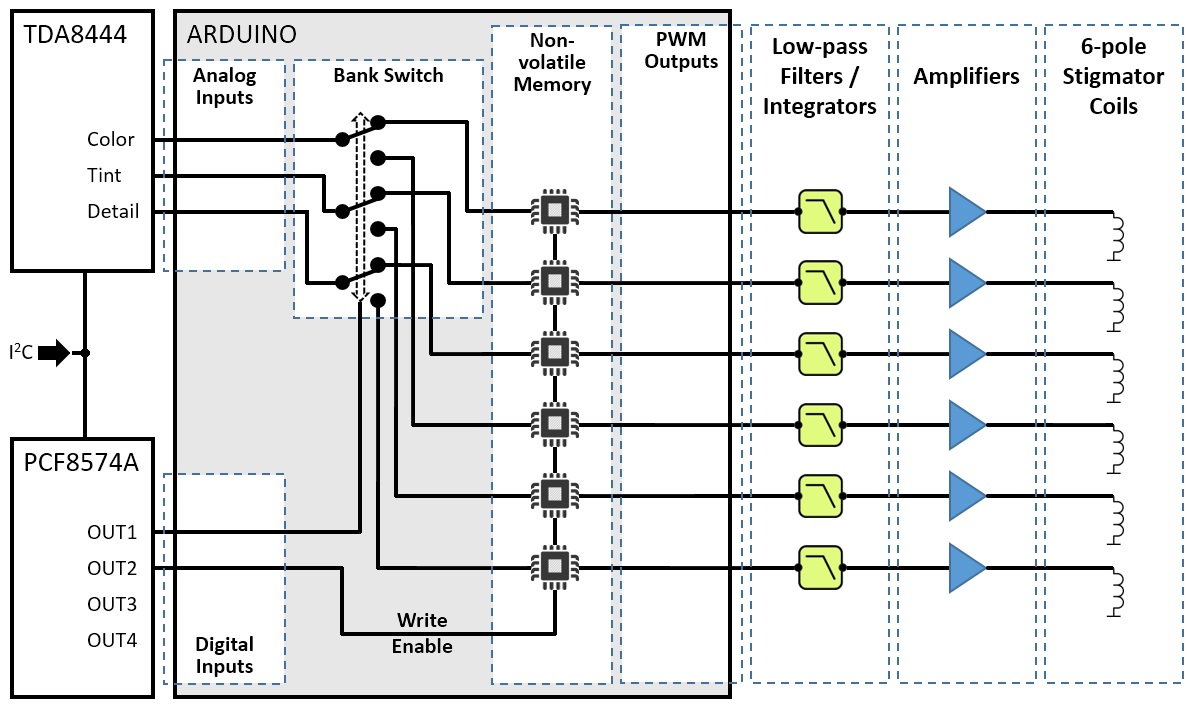
Hi,
There's a solution to this. On the (emulated) Decoder board there's another I2C device (PCF8574A) which does some switching. It is controlled via the Decoder Options in the menu. If You use its outputs together with the three analog signals, You can feed an Arduino and with a few lines of code it will deliver enough outputs. The image below shows the basic idea behind it...
Regards,
barclay66
| Description: |
|
| Filesize: |
192.93 KB |
| Viewed: |
7162 Time(s) |
|
|
|
| Back to top |
|
|
gjaky
Joined: 05 Jun 2010
Posts: 2802
Location: Budapest, Hungary
|
| Posted: Wed Jul 06, 2016 3:58 pm Post subject: |
|
|
Horizontal stigmator correction waveform has the same frequency as the scanrate, so even for 60kHz scanrate that would need pretty fast PWM output, isn't that a problem for Arduino?
_________________
projectors in the past : NEC 6-9PG xtra, Electrohome Marquee 6-7500, NEC XG 1351 LC ( with super modified Electrohome VNB neckboard !!!)
current: VDC Marquee 9500LC
The MOD: VNB-DB, VIM-DB
|
|
| Back to top |
|
|
cmjohnson
Joined: 03 Apr 2006
Posts: 5180
Location: Buried under G90s
|
| Posted: Wed Jul 06, 2016 5:20 pm Post subject: |
|
|
Actually, astig has to make up to three corrections per scan line. Left side, middle, right side.
But I'm not going to follow this approach anyway. It's way more effort than it takes just to create a 12 channel bipolar DC power supply board with a bunch of 1K adjustment pots on itr.
|
|
| Back to top |
|
|
gjaky
Joined: 05 Jun 2010
Posts: 2802
Location: Budapest, Hungary
|
| Posted: Wed Jul 06, 2016 6:40 pm Post subject: |
|
|
| cmjohnson wrote: | Actually, astig has to make up to three corrections per scan line. Left side, middle, right side.
But I'm not going to follow this approach anyway. It's way more effort than it takes just to create a 12 channel bipolar DC power supply board with a bunch of 1K adjustment pots on itr. |
Still you have to create the right signal shape in-phase with the other correction signals.
_________________
projectors in the past : NEC 6-9PG xtra, Electrohome Marquee 6-7500, NEC XG 1351 LC ( with super modified Electrohome VNB neckboard !!!)
current: VDC Marquee 9500LC
The MOD: VNB-DB, VIM-DB
|
|
| Back to top |
|
|
barclay66
Joined: 27 Jun 2011
Posts: 1304
Location: Germany
TV/Projector: Marquee 9500 Ultra
|
| Posted: Wed Jul 06, 2016 8:59 pm Post subject: |
|
|
Hi,
| cmjohnson wrote: | As for the electronic CPC rings on a G90, those are only driven by DC voltages provided by the 12 channel DC supply on the G90 DF board. Rail voltages are only +/-6 volts.
Actually coming up with a system to drive the G90's electronic CPC rings would be the simplest of any possible project if you wanted to add functional magnetics to a Marquee that were unique to a different projector. Not saying it would be an afternoon's work, but it's functionally only a dozen variable DC sources at low voltage. It could be done with a DC power supply and a handful of trim pots. |
If this is correct, the approach with the Arduino will work. If there are any waveforms involved, those would have to be generated with some additional circuitry and the Arduino could be used for controlling their amplitude...
Regards,
barclay66
|
|
| Back to top |
|
|
cmjohnson
Joined: 03 Apr 2006
Posts: 5180
Location: Buried under G90s
|
| Posted: Wed Jul 06, 2016 9:11 pm Post subject: |
|
|
We're getting mixed up.
You're talking about the active electronic astig that would drive the 6 pole astig windings in the focus yoke,
and I was referring to the electronic CPC rings which only need DC.
I wouldn't start investing the time to build the 6 pole astig driver until I did my "borrow a channel" experiment and found if the juice was worth the squeeze.
I'd rather work on the electronic CPC driver board first, because I've already started down that path.
Anyway, I've figured out MOST of what's needed to properly run G90 deflection yokes off the Marquee HDM.
Tse helped me find one of the keys to the kingdom.
R175 on the HDM, located under the daughter board, determines the gain of the deflection amplifier system. It's a measly little 1/8 watt conventional thru-hole resistor, with a stock value of 357 ohms. Increasing its value reduces the current drive in the amplifier system, which means smaller rasters.
I tried a few experimental values and found that when I replaced R175 with an 809 ohm resistor (the only value I had in the upper hundreds) then I'd say that the G90 deflection yoke delivered the perfect range of raster width, with overscanning the CRT face being possible with size in the upper 90s.
But it would still not run in the green circuit as it was still running too much current.
So I added series inductors to both coils of the yoke. (Actually did it on the HDM itself. Much easier than modifying a wiring harness.)
Long story short, the green channel of the HDM, the one with the current sense circuit on it, is happy to run with the G90 deflection yoke if you add some inductance in series with the yoke. I know that 120 µH or more added inductance is sufficient, at least as far as my test unit is concerned. But since I lack a lot of inductor choices that are small enough to allow me to fine tune that value, or large enough to be useful, I need to go out and get a few more inductors in the right sizes and types to allow me to refine this experiment. I need to pick up a handful in inductance values up to maybe 47 µH and start figuring it out.
The more inductance is added, the more the raster shrinks. Of course, the inductors are converting some of the signal to heat.
So I then have to lower the value of R175.
It's interesting to note that if I didn't balance BOTH coils in the deflection yoke with equal added inductors, I got raster ringing and it was VERY visible.
This by itself creates a very, very interesting possibility: That one cause of raster ringing is an imbalance in the inductance of the deflection coils.
Which, all by itself, suggests that if you have raster ringing issues, it MAY be possible to eliminate raster ringing by incorporating a suitably sized variable inductor (Very small value) on one or both coil circuits and tuning them to cancel out any visible raster ringing.
I think that might be worth trying.
I'm back at the stock value for R175 for now, and may have to go with LOWER values. Hopefully it'll all balance out, so that I'm not overdriving the H. drive amplifier when I find the minimum acceptable added inductance value for the yoke.
I may end up having to improve the cooling in the HDM by adding a fan or two at the ends of the HDM cage. Punch out some holes in the ends of the cage, add fans, not very difficult.
And then, modify the current sense circuit to be more permissive. And rely on improved cooling to keep the HDM from burning out.
This might get tricky.
|
|
| Back to top |
|
|
CIR Engineering
Joined: 25 Aug 2008
Posts: 4269
Location: Chicago USA & Berlin Germany
|
| Posted: Thu Jul 07, 2016 7:25 pm Post subject: |
|
|
I wonder if the Sony DY's will reduce the raster ringing on the Marquee... The G90 has the least amount of raster ringing of any CRT and if you move the image to the bottom left of the raster you get almost none on screen. The raster ringing on the Marquee has always been really problematic so fingers crossed that you will improve it.
craigr
_________________
JETI 1501-HiRes 2nm Spectroradiometer
JETI 1211 Spectroradiometer
Photo Research PR-650 Spectroradiometer
Klein K10-A Colorimeter
Murideo Fresco SIX-G HDMI 2.x Multimedia Generator
Murideo Fresco SIX-A HDMI 2.x Analyzer
Light Illusion ColourSpace XPT Color Calibration Software
Light Illusion LightSpace XPT Pro Version 10.x Color Calibration Software
OMARDRIS JVC Software Patch to use K10-A and Jeti with JVC OEM AutoCal Software!
Sencore CR7000 CRT Tube Analyzer / Rejuvenater
Authorized Dealer for Lumagen & just about everything worth buying
www.CIR-Engineering.com - craigr@cir-engineering.com
Phone: 865-405-6892
|
|
| Back to top |
|
|
cmjohnson
Joined: 03 Apr 2006
Posts: 5180
Location: Buried under G90s
|
| Posted: Fri Jul 08, 2016 2:54 am Post subject: |
|
|
I'm thinking that adding a pair of small variable inductors in series with the Thomson deflection yokes, one at the start of one coil and one at the end of the other, and tuning them, could possibly reduce or eliminate raster ringing. The values of the inductors should be small, ideally not any larger than needed to be able to balance the coils. Voltage and current ratings do need to be considered.
I've ordered all the parts I need to (hopefully) complete the G90 deflection yoke experiment. They should all be here in a few days.
|
|
| Back to top |
|
|
cmjohnson
Joined: 03 Apr 2006
Posts: 5180
Location: Buried under G90s
|
| Posted: Mon Jul 18, 2016 9:15 pm Post subject: |
|
|
Now upon careful consideration I think that the answer to running G90 deflection yokes in a Marquee is to use a matching transformer
between the HDM and the G90 yoke. It'd have to be moderately broadband, able to support the bandwidth needed for any scan rate we'll actually need (call it maybe 75 KHz plus retrace pulses) (1080p-72) and have a turns ratio of about 3.5 to 1, which matches the ratio of G90 coil inductance to Marquee coil inductance. (80 µH vs. 280 µH)
Plus it needs to be bifilar wound, or have two separate sections, as each yoke has two H. windings.
|
|
| Back to top |
|
|
|
|


