| Author |
Message |
jaredjaric
Joined: 05 Jun 2007
Posts: 228
Location: Philippines
|
| Posted: Thu Sep 02, 2010 1:32 pm Post subject: quadrupler rectifier circuit |
|
|
This came from a pj with no hv,replaced 3 eht still no HV,changed the quad and the quad did the trick.So definitely this is a bad quad.But...I opened up the quad and took out eht circuit to check for bad diodes, found none ,had a tech guy checked the tranny ,no open circuit,all the caps also seem fine.
My question is ,why would this quad fail when all the diodes and caps seem ok ?
| Description: |
|
| Filesize: |
15.18 KB |
| Viewed: |
11743 Time(s) |
|
|
|
| Back to top |
|
 |
jaredjaric
Joined: 05 Jun 2007
Posts: 228
Location: Philippines
|
| Posted: Thu Sep 02, 2010 2:26 pm Post subject: cine 9 quad |
|
|
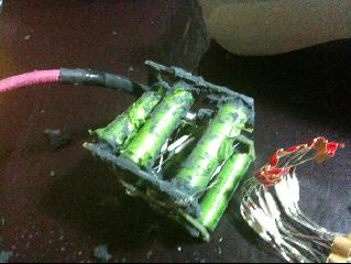
this is a cine 9 quad,which i plan to rebuild if advisable. 
|
|
| Back to top |
|
|
macgyver655
Joined: 22 Aug 2007
Posts: 8508
|
| Posted: Thu Sep 02, 2010 3:53 pm Post subject: |
|
|
|
Is that transistor a mosfet?
|
|
| Back to top |
|
|
jaredjaric
Joined: 05 Jun 2007
Posts: 228
Location: Philippines
|
| Posted: Thu Sep 02, 2010 4:06 pm Post subject: |
|
|
| macgyver655 wrote: | | Is that transistor a mosfet? |
Good day Mac,
there are no transistor in the pic just caps and diodes. 
|
|
| Back to top |
|
|
Curt Palme
CRT Tech
Joined: 08 Mar 2006
Posts: 24396
Location: Langley, BC
TV/Projector: All of them!
|
| Posted: Thu Sep 02, 2010 4:30 pm Post subject: |
|
|
|
You're most likely measuring the parts with 1-10 volts applied. Parts do strange things once under a 34Kv supply. Unless you're running these at the specified voltages, you will probably not read what the fault is. I'd simply replace all caps and diodes, and I'm sure you're running again.
|
|
| Back to top |
|
|
Tom.W

Joined: 09 Mar 2006
Posts: 6635
|
|
| Back to top |
|
|
jaredjaric
Joined: 05 Jun 2007
Posts: 228
Location: Philippines
|
| Posted: Fri Sep 03, 2010 1:06 am Post subject: |
|
|
| Curt Palme wrote: | | You're most likely measuring the parts with 1-10 volts applied. Parts do strange things once under a 34Kv supply. Unless you're running these at the specified voltages, you will probably not read what the fault is. I'd simply replace all caps and diodes, and I'm sure you're running again. |
thanks Curt.Sorry for not replying right away,fell asleep last night.
I have a question with regards to the transfo,you think the transformer from an old 808 can do work?
|
|
| Back to top |
|
|
jaredjaric
Joined: 05 Jun 2007
Posts: 228
Location: Philippines
|
| Posted: Fri Sep 03, 2010 1:18 am Post subject: |
|
|
the diodes and caps are rated at 14 kV and 10kv respectively.you think these parts are sufficient enough,the local tech guy here suggests to try to look for higher rated parts.
I am looking at good quality silicone,Cause it is reversible.I can cut and slowly carve out the silicone with out breaking the Quad case.But many have advised against it,this is an experiment worth taking for me,so i will go for it and let you guys know.
Thanks for the web address
|
|
| Back to top |
|
|
macgyver655
Joined: 22 Aug 2007
Posts: 8508
|
| Posted: Fri Sep 03, 2010 1:31 am Post subject: |
|
|
| jaredjaric wrote: | | macgyver655 wrote: | | Is that transistor a mosfet? |
Good day Mac,
there are no transistor in the pic just caps and diodes. |
Oh, I thought tranny meant transistor. Of course thought other things too, eeeeeeeeeeeewwwwwwhhhhh!!!!!!!!!!!!!!!
If we dont hear back from you then I guess the silicon didn't work!!!!!! 
I think its a BAAAAAAAAAD, idea.
|
|
| Back to top |
|
|
Tom.W
Joined: 09 Mar 2006
Posts: 6635
|
|
| Back to top |
|
|
jaredjaric
Joined: 05 Jun 2007
Posts: 228
Location: Philippines
|
| Posted: Fri Sep 03, 2010 8:51 am Post subject: |
|
|
I went to my favorite EE guy,to have the transfo thoroughly checked,there was a crack on the ferrite core,but seems minor and might not affect its use.He will put a dummy load on the quad to see if the parts are up to par.Also planning to upgrade the diodes and caps,will let you guys know...
Mac ,you are right ,must not use the T term anymore :0
TOm,thanks again.
|
|
| Back to top |
|
|
wingnut2001
Joined: 25 Aug 2010
Posts: 37
Location: Horse City of the world!
|
| Posted: Fri Sep 10, 2010 2:31 am Post subject: |
|
|
|
I tried to get 2 quads apart to rebuild them myself but was unsuccessful, there ain't much to them and they should be able to be custom made if one could get a exact part list and diagrams, the transformer inside is what would be the kicker, the 2 quads I took apart the core around the transformer cracked, hope someone can figure this out, making quads would save many a barco!!
|
|
| Back to top |
|
|
Tom.W
Joined: 09 Mar 2006
Posts: 6635
|
| Posted: Fri Sep 10, 2010 2:44 am Post subject: |
|
|
|
The potting compound used by Barco is a real bear to remove as you well know by now...
|
|
| Back to top |
|
|
jaredjaric
Joined: 05 Jun 2007
Posts: 228
Location: Philippines
|
| Posted: Fri Sep 10, 2010 4:30 pm Post subject: |
|
|
| wingnut2001 wrote: | | I tried to get 2 quads apart to rebuild them myself but was unsuccessful, there ain't much to them and they should be able to be custom made if one could get a exact part list and diagrams, the transformer inside is what would be the kicker, the 2 quads I took apart the core around the transformer cracked, hope someone can figure this out, making quads would save many a barco!! |
the cracked core would still work,but would hum,vibrate like crazy,and so with my quad i am thinking of sending the transformer to an oem supplier in China.i will update the outcome,
the caps are 10kv rated polystyrene,and the rectifiers will be using 16kv.hoping to get it right.
|
|
| Back to top |
|
|
zGman
Joined: 22 May 2006
Posts: 599
|
| Posted: Fri Sep 10, 2010 4:36 pm Post subject: |
|
|
I wonder if the transformer is what breaks down under HV? Seems like it is
the component with the most electrical stress, and quite likely some
mechanical stress as well (yes - rapidly changing electromagnetic fields
create physical force - think motors, or feel an old buzzing x-former)
There is also heat - so add up the breakdown of insulation over time, with heat
and physical stress, possibly the windings start to short, possibly feeding
back HV into the EHT or changing the load profile.....
G
|
|
| Back to top |
|
|
jaredjaric
Joined: 05 Jun 2007
Posts: 228
Location: Philippines
|
| Posted: Fri Sep 10, 2010 4:37 pm Post subject: |
|
|
| Tom.W wrote: | | The potting compound used by Barco is a real bear to remove as you well know by now... |
yes it is,but it is worth trying.
i use carving tools to scrape off the silicon ,piece by piece but still manage to crack the transformer core.but i think one can get better on it.
|
|
| Back to top |
|
|
jaredjaric
Joined: 05 Jun 2007
Posts: 228
Location: Philippines
|
| Posted: Fri Sep 10, 2010 4:53 pm Post subject: |
|
|
| zGman wrote: | I wonder if the transformer is what breaks down under HV? Seems like it is
the component with the most electrical stress, and quite likely some
mechanical stress as well (yes - rapidly changing electromagnetic fields
create physical force - think motors, or feel an old buzzing x-former)
There is also heat - so add up the breakdown of insulation over time, with heat
and physical stress, possibly the windings start to short, possibly feeding
back HV into the EHT or changing the load profile.....
G |
all the parts passed the dummy load test,but i dont think the tech guy used enough voltage(no heat stress maybe).but he is suggesting tiny cracks in the quad case causing it to short.i do remember smelling of burning caps in the pj before,it is possible over a long period of use the insulation breaks down and arcs would burn holes on the plastics,...i think.
|
|
| Back to top |
|
|
zGman
Joined: 22 May 2006
Posts: 599
|
| Posted: Fri Sep 10, 2010 5:02 pm Post subject: |
|
|
It would be interesting to see the waveform the EHT is sending to the Quad...
It seems possible that if it is not a smooth sine wave profile, that the additional
high frequency components would cause more stress on the x-former and other
components...
G
|
|
| Back to top |
|
|
jaredjaric
Joined: 05 Jun 2007
Posts: 228
Location: Philippines
|
| Posted: Fri Sep 10, 2010 5:28 pm Post subject: |
|
|
| zGman wrote: | It would be interesting to see the waveform the EHT is sending to the Quad...
It seems possible that if it is not a smooth sine wave profile, that the additional
high frequency components would cause more stress on the x-former and other
components...
G |
i remember the tech guy using the oscilloscope on the eht,and saying something about the square wave which i dont understand.
with hi frequency component,are you referring to the diodes?
|
|
| Back to top |
|
|
zGman
Joined: 22 May 2006
Posts: 599
|
| Posted: Fri Sep 10, 2010 6:05 pm Post subject: |
|
|
Try this link for an overview....
http://en.wikipedia.org/wiki/Fourier_series
Basically, as I understood it (so very long ago), a square wave
can be thought of as a construction of various frequency sine/cosine
waves. This has some real consequences, as the sharper the "corner"
of the square ware, the higher the amplitude and frequency of the
'component' sine/cosine waves. Tranformers are designed to work
at a nominal frequency, based on the magnetic permeability of the
core, etc etc..... So - running a square ware into a transformer is
going to create heat and inefficiency and stress, which could lead
to premature failure...
G
|
|
| Back to top |
|
|
|
|


