| Author |
Message |
cmjohnson

Joined: 03 Apr 2006
Posts: 5180
Location: Buried under G90s
|
| Posted: Sat May 22, 2010 2:06 am Post subject: Inside the legendary G90 focus yoke |
|
|
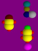
Here are some pics of the internals of the focus yokes used on the Sony VPH-G90U projector.
I have no electrical measurements as of yet.
This is an extension of the classic Kanto-Denshi design, essentially built with larger coils, presumably for greater
current handling capacity, greater magnetic field strength over a longer distance down the neck, and presumably,
greater beam control without scattering.


I'll have to spend some time with a meter to see what the electrical parameters of the coil are, and also
I'll get the magnetic field strength measured to see how it might work in a Marquee.
Will these be any better in a Marquee than the Advanced (optimized) FrankenYokes?
I don't know. POSSIBLY. The long coil lengths seem to be promising. BUT, that raises questions about neck space,
as there's only so much neck length to work with. Saving space may be required.
How would this be achieved? Well, I got the deflection yokes off the G90 as well as ALL the other G90 magnetics,
and the G90's deflection yoke is a precision piece of the yoke winder's art with integral convergence coils in the
same assembly. This assembly is shorter than a regular Marquee deflection and convergence yoke pair, and
if they measure out close enough electrically, I may opt to try them out in a Marquee as well. I don't think that
it would do any harm to attempt this. I can't see why it wouldn't work perfectly, as long as the electrical parameters
of the deflection and convergence coils are close enough to Marquee value requirements.
Since I also intend to experiment with the active CPC coil assemblies from a G90, and try them out in a Marquee using
some small adjustable DC power supplies, it stands to reason that by the time I'm done with this round of experiments,
I may end up running a COMPLETE set of G90 magnetics in a Marquee.
I will be sure to keep this topic up to date as I get some more data and results.
Anyone who is following this same line of experimentation is of course welcome to add their own data as well.
I would say right now that ALL magnetics from any scrapped G90 should be saved, at least for now. They are all
interesting and promising from what I can see so far.
We've read (and some of us have seen for ourselves) that a well set up G90 projecting a test grid looks like the
grid was drawn by laser. I can't see why a suitably modded Marquee can't be as good.
CJ
|
|
| Back to top |
|
 |
cmjohnson
Joined: 03 Apr 2006
Posts: 5180
Location: Buried under G90s
|
| Posted: Sat May 22, 2010 2:34 am Post subject: |
|
|

Here's a photo of both G90 and Marquee magnetic stacks. You can see for yourself how much difference there is in terms of
tube neck real estate. I THINK that I can still get the Marquee neck card cage installed with the G90 magnetic stack, but
I haven't actually tried it out yet.
CJ
|
|
| Back to top |
|
|
Mark_A_W
Joined: 15 Mar 2006
Posts: 3068
Location: Sunny Melbourne Australia
|
| Posted: Sat May 22, 2010 9:10 am Post subject: |
|
|
Are the Marquee Astig magnets really meant to be that far forward?
Surely they should be over the smooth tube part of the electron gun, where the G90 ones are (and XG and G70..)?
|
|
| Back to top |
|
|
cmjohnson
Joined: 03 Apr 2006
Posts: 5180
Location: Buried under G90s
|
| Posted: Sat May 22, 2010 2:00 pm Post subject: |
|
|
|
I stacked them touching each other only to show how much tube real estate the various coils use. This is not meant to represent an actual running configuration.
|
|
| Back to top |
|
|
cmjohnson
Joined: 03 Apr 2006
Posts: 5180
Location: Buried under G90s
|
| Posted: Tue May 25, 2010 11:40 pm Post subject: |
|
|
More information, now edited to add a little more data.
I have learned that the long yellow inner coil contains two astig assemblies: A 4 pole astig assembly AND a 6 pole assembly, each occupying half the length of the former. The G90 has both 4 pole and 6-pole astig windings and here they are.
This poses an interesting option: Since both the 4-pole and 6-pole astig windings both use two pairs of wires as they are both wired with two coil phases, there is probably no technical reason why you couldn't use EITHER the 4-pole OR 6-pole astig windings in a Marquee.
You would simply attach an astig cable to EACH set of astig windings and try one and then try the other. Use the one that works better and leave the other one hanging loose.
I've obtained another LCR meter BUT its value ranges don't go down into the microhenry range which is needed to measure the dynamic coil's inductance value. But I can measure the static coil's value.
I will give the DC resistance values for the various coils and their function, if known.
Yellow outer coil: 78.5 ohms, connects to yellow and green wires on 5-pin connector. Static focus.
Red outer coil: 0.3 ohms (approximately, my meter leads are actually a higher resistance reading.), red and blue wires on 5-pin connector. Dynamic focus. This is a siamesed coil, with two halves of the winding on one spool with a partition between them. This is the long dual red coil shown in the pictures.
Its inductance value on all three G90 yokes is between 46 and 48 milliHenries so I'm going to say it's a nominal 47 mH coil.
Yellow inner coil assembly: 4-pole and 6-pole astig windings. They are built as ring-shaped coils that are taped around the circumference of the coil former. Think of windows going around the side of a round building. There are 8 such coils for the
4-pole astig circuit and 12 such coils for the 6-pole astig circuit. The inductance value of this coil is not really of
any importance to us as we're not likely to even THINK about changing them. Either they'll work satisfactorily,
or they won't. If the won't, then the G90 yoke simply isn't a reasonable candidate for Marquee usage. I tend to
think that they WILL work.
6-pole pairs are grey-brown and orange-white. 5.5 ohms. Each pair consists of 6 coils wired out of phase with the other pair. Same comment on inductive value as above.
4-pole pairs are green-blue and red-yellow. 4.7 ohms. Each pair consists of 4 coils wired out of phase with the other pair. Same comment on inductive value as above.
For Marquee use, you would not do anything to the astig coils. The dynamic and static focus coils may have to be rewound to the
appropriate inductance values, depending on their current values.
CJ
Last edited by cmjohnson on Sat Jun 05, 2010 11:43 pm; edited 1 time in total
|
|
| Back to top |
|
|
CIR Engineering

Joined: 25 Aug 2008
Posts: 4269
Location: Chicago USA & Berlin Germany
|
| Posted: Wed May 26, 2010 1:58 pm Post subject: |
|
|
One problem you may have with adapting the G90 coils is that the G90 has dynamic adjustment of the 4 and 6 pole magnets at the center and also eight additional quadrants around the screen (for each color).
If you adapt the G90 magnets to an existing Marque design, you will loose the zone adjustments for either the 4 or six pole magnets. May not be a big deal, but it is one feature of the G90 that will not carry over to the Marquee.
craigr
_________________
JETI 1501-HiRes 2nm Spectroradiometer
JETI 1211 Spectroradiometer
Photo Research PR-650 Spectroradiometer
Klein K10-A Colorimeter
Murideo Fresco SIX-G HDMI 2.x Multimedia Generator
Murideo Fresco SIX-A HDMI 2.x Analyzer
Light Illusion ColourSpace XPT Color Calibration Software
Light Illusion LightSpace XPT Pro Version 10.x Color Calibration Software
OMARDRIS JVC Software Patch to use K10-A and Jeti with JVC OEM AutoCal Software!
Sencore CR7000 CRT Tube Analyzer / Rejuvenater
Authorized Dealer for Lumagen & just about everything worth buying 
www.CIR-Engineering.com - craigr@cir-engineering.com
Phone: 865-405-6892
|
|
| Back to top |
|
|
cmjohnson
Joined: 03 Apr 2006
Posts: 5180
Location: Buried under G90s
|
| Posted: Wed May 26, 2010 2:20 pm Post subject: |
|
|
BUT...I can use EITHER the 4-pole OR the 6-pole astig windings with a Marquee. Not both at once, but either one.
I think that the 6-pole astig adjustment alone should work better than the 4-pole adjustment alone, so this is a net gain
for astig control for the Marquee.
I can't use everything but what I can use should be an improvement. I'll take a net gain when it's available.
CJ
|
|
| Back to top |
|
|
tse
Joined: 03 May 2006
Posts: 1014
Location: Sweatbucket, Fl.
|
| Posted: Thu May 27, 2010 1:48 am Post subject: |
|
|
Most likely the greatest gain will come from the two four pole stig windings. The CRT has an inherent spot distortion everywhere except the center because the beam hits the screen at an angle which causes an eliptical spot shape. The spot can be corrected to round by the + (or "y") windings or the x (or "x") windings of the dynamic stig correction system. The two six pole windings are good for correcting trianglular spot shapes but most CRTs don't have that problem. I don't know why the triangular spots happen.
Scott
| Description: |
|
| Filesize: |
3.59 KB |
| Viewed: |
14440 Time(s) |
|
_________________
"Were we directed from Washington when to sow and when to reap, we would soon want bread."
Thomas Jefferson
|
|
| Back to top |
|
|
cmjohnson
Joined: 03 Apr 2006
Posts: 5180
Location: Buried under G90s
|
| Posted: Thu May 27, 2010 3:36 am Post subject: |
|
|
My suspicion is that triangular spots are sometimes caused by defective or weak 6-pole adjustments in a CPC pack that is so equipped.
I know I've seen that on my OWN projector in the past, when I was learning how to convert "blank" unused CPC ring sets into 6-pole sets, which I eventually learned to do with a pretty good level of success and quality. I now round up all the 2-pole and 2/4 pole CPC sets
I can get my hands on and degauss extra ring pairs and then remagnetize them to make 2/4/6 pole sets. If they test as well as new
factory made ones, I'll offer them for sale in sets.
Incidentally, this means that I'll take (or even buy) ANY sets of CPC rings that anyone has lying around surplus. 2 pole, 2/4 pole,
it doesn't matter. If they're the right size to fit Panny tubes, I'll take 'em at the right price. They will become part of 2/4/6 pole sets
the next time I make up a few batches.
CJ
|
|
| Back to top |
|
|
CIR Engineering
Joined: 25 Aug 2008
Posts: 4269
Location: Chicago USA & Berlin Germany
|
| Posted: Thu May 27, 2010 12:54 pm Post subject: |
|
|
I think the 4-pole G90 magnets will do more good than the 6-pole as well.
However, the strength of the G90 magnetic system isn't just in the magnets themselves, it's in the complete hardware package including the dynamic control of the magnets at the nine quadrants on the screen. Presently, you can use a regular old CPC magnet set to do 2, 4, and 6-pole adjustments at the center of the screen on a Marquee. If you change to a G90 magnet set, you might be able to do pretty much the same thing, but just control it electronically.
The G90 memory system allows for a unique 2-pole adjustment at the center of the screen for each scan rate (memory). It also allows for independent 4-pole at nine quadrants for each memory. And then the G90 also allows for a 6-pole adjustment at nine quadrants that applies universally to all input frequencies. On the Marquee you don't have 2-pole adjustments in the service menu and you also don't have 6-pole adjustments. So when you set the 2-pole with the G90 magnets in the Marquee you are going to have a single 2-pole setting again unless you manage to rig up a complete control system for the 2-pole assemblies that changes with input scan rate...
Usually on a Marquee when I see triangulation it is at the sides of the image, and it is not evenly distributed triangulation across the entire screen. I just don't see the 6-pole magnets working well without control at all nine quadrants. I suppose that if you happen to come across a set that has naturally good astigmatism and doesn't need a lot of 4-pole adjustments that you could maybe opt to use just the 6-pole magnets in place of the Marquee 4-poles, but this will probably not be a rule for many projectors.
craigr
_________________
JETI 1501-HiRes 2nm Spectroradiometer
JETI 1211 Spectroradiometer
Photo Research PR-650 Spectroradiometer
Klein K10-A Colorimeter
Murideo Fresco SIX-G HDMI 2.x Multimedia Generator
Murideo Fresco SIX-A HDMI 2.x Analyzer
Light Illusion ColourSpace XPT Color Calibration Software
Light Illusion LightSpace XPT Pro Version 10.x Color Calibration Software
OMARDRIS JVC Software Patch to use K10-A and Jeti with JVC OEM AutoCal Software!
Sencore CR7000 CRT Tube Analyzer / Rejuvenater
Authorized Dealer for Lumagen & just about everything worth buying
www.CIR-Engineering.com - craigr@cir-engineering.com
Phone: 865-405-6892
|
|
| Back to top |
|
|
Nashou66

Joined: 12 Jan 2007
Posts: 16171
Location: West Seneca NY
|
|
| Back to top |
|
|
dvh99
Joined: 25 Dec 2009
Posts: 2158
Location: nederland
|
| Posted: Thu May 27, 2010 7:37 pm Post subject: |
|
|
that was indeed informative, i wonder how much 4 pole vs 6pole differs in real life.
is this to be made visible in test patterns.
_________________
1 answer always poses multiple questions.
marquee 9500ultra HD10L moome hdmi1.3 v3+ some mods.
|
|
| Back to top |
|
|
Tom.W

Joined: 09 Mar 2006
Posts: 6635
|
| Posted: Thu May 27, 2010 8:07 pm Post subject: |
|
|
| Nashou66 wrote: | Here is a great paper on magnetics , the electron beam, and CRT. the company still exists and makes deflection yokes and focus coils etc.
http://celco-nj.com/SID_Paper01.htm
Athanasios |
Thanks for the link. 
|
|
| Back to top |
|
|
CRT_Ben
Joined: 28 Aug 2006
Posts: 1684
Location: Northern Virginia
|
| Posted: Thu May 27, 2010 8:26 pm Post subject: |
|
|
|
Wow, great link!! Lots of fantastic info presented without being dry.
|
|
| Back to top |
|
|
Nashou66
Joined: 12 Jan 2007
Posts: 16171
Location: West Seneca NY
|
|
| Back to top |
|
|
JustGreg

Joined: 07 Mar 2006
Posts: 3098
Location: Kenosha, WI
|
| Posted: Fri May 28, 2010 4:18 am Post subject: |
|
|
Hell yeah!...a great read.  I actually kept up and didn't fall asleep (and bend my glasses) like I usually do reading white papers. I actually kept up and didn't fall asleep (and bend my glasses) like I usually do reading white papers. 
How cool would it be if CJ could hook up with one of the eggheads from Celco to modify/update our beam controls.
I've been reading for years about people that just can't get a good resolve, eg, spot shape couldn't be reined in regardless of pj brand.
That article seemed to me to point to a lack of quality (read=attention to detail) when designing and/or building the CRT. That would be an unrecoverable situation without replacing the tube. I wonder how many people tore their hair out over the years trying to resolve good spots and all along it was the tubes.
Yup...very informative and written for the math impaired to boot.
_________________
Greg
"Is it ignorance or apathy? Hey, I don't know and I don't care!" --Jimmy Buffett
|
|
| Back to top |
|
|
cmjohnson
Joined: 03 Apr 2006
Posts: 5180
Location: Buried under G90s
|
| Posted: Fri May 28, 2010 10:35 pm Post subject: |
|
|
Just to mention it, the Marquee does have dynamic astigmatism adjustment, so the G90 is not unique in that respect, however,
the G90 does have both active 4-pole AND active 6-pole astig adjustment while the Marquee only has active 4-pole astig adjustment.
When I finish optimizing my test set of G90 yokes for inductance values and magnetic strength, I will of course try out both the 4-pole
and 6-pole astig coils with the Marquee's astig circuitry and see for myself which is better in a Marquee.
The unit in question will of course be equipped with full-featured 2/4/6 pole CPC rings as well.
A future planned test is to provide variable power supplies to drive G90 electronic CPC rings just to see how they interact. If they
work particularly well, I'll attempt to turn it into a workable project kit. I would not personally even object to adding a small control
box on the top sheet metal cover of my PJ, containing the adjustment potentiometers, which I'm sure would be 10 turn precision pots
in appropriate values. All those rings need is the appropriate DC voltages in correct polarities. I can figure out what those specs
actually are, with a little work.
As for the beam shape in the corners, it's always related to the deflection angle where the beam intersects the glass. One possible cure would be to make the CRT faces out of thick fiber optic glass with a concave inner surface which keeps the beam travel distance constant from the center of deflection (at the deflection coil) to the inner CRT face. It would be a deep dish shaped faceplate, as seen
from the inside. Fiber optics would transfer a very clean dot profile to the front glass.
But, that would be a hideously expensive tube. The faceplate alone would probably cost multiple thousands of dollars as fiber optic
glass blocks are anything but cheap.
If I were in a position to modify or update the Marquee's beam controls, it WOULD be nice to add more control channels such as active
6-pole astig and active CPC coils, like the G90. But the deflection and dynamic focus systems that the Marquee uses are very
sophisticated in and of themselves. The dynamic focus system is an efficient resonant drive system, and the deflection system is also a
resonant drive system. These two factors alone are part of the reason why Marquees don't have such aggressive fan cooling systems
as some other projectors and run cooler as well. But it also explains why incorrect focus yokes don't quite achieve their perfomance potential as their inductive values must be correct in order for the resonant focus system to operate efficiently and transfer current to the focus coils as they're intended to do.
What I would like to see modified is the convergence system. In my opinion it needs finer control and more zones of control, too. The
minimum convergence adjustment shift is more than a pixel wide at 1080p and that's just not quite good enough.
I've figured out that IF your projector has a great deal more total convergence range than you need, then the entire convergence
adjustment range can be reduced considerably, which would affect the fineness of all convergence changes. It would give you finer
control but at the loss of some of your total range of convergence. It'd be done by modifying the convergence amplifier gain or input
level signals.
CJ
|
|
| Back to top |
|
|
cmjohnson
Joined: 03 Apr 2006
Posts: 5180
Location: Buried under G90s
|
| Posted: Sat Jun 05, 2010 11:44 pm Post subject: |
|
|
I've updated my earlier description with the static coil's inductance value, which is nominally 47 mH, and too high for the Marquee
focus circuit to work efficiently. It should be trimmed down to 30 mH.
HOWEVER...if the magnetic strength of the coil assembly is right and the central focus is very good with the focus
coil UNPLUGGED, then perhaps you can get away with having an off value static coil. I would not recommend it,
but IDEALLY the coil just sits there and is essentially unused as the strength of the coil's magnets are ideal.
But the value of the dynamic coil SHOULD be as close to the design value of 45 microHenries as possible, as it DOES
matter. The dyamic focus system is a resonant circuit and it must be in resonance for the focus amplifier to deliver
maximum current at minimum voltage, and if it's off value, the amp will run hot and may not have enough available
power to establish correct focus.
The way this works is that the static coil is the inductance, and the drive circuit switches capacitors in and out of the
circuit according to the scan rate range, providing the capacitance for a tuned resonant tank circuit.
What's interesting here is that if you know your LRC circuit math, you could calculate the IDEAL values for any
specific scan rate and then customize the focus board's capacitor values and dynamic focus coil's inductance
value to make the focus circuit HIGHLY efficient at any specific scan rate(s) that you cared to calculate for.
The capacitor values that are switched in and out of the circuit according to scan frequency are:
22 nF
68 nF
2.2 uF
and they are switched in parallel with a 33 nF cap that is always in the circuit.
So, the capacitive values in total, depending on the scan frequency range, are:
55 nF
101 nF
2233 nF
and the inductance value is 45 uH.
This gives resonance at (In order)
101 KHz
74.6 KHz
15.8 KHz
1080p-60 requires a horizontal scan frequency of 67.54 KHz.
So, calculating the capacitance value required if you don't adjust the inductor value gives an ideal capacitance value of:
123.4 nF
Since there's already a 33 nF cap in the circuit, you'd need to switch 90 nF into the circuit. Add a 22 nF cap in parallel
with the 68 nF cap and you're perfectly balanced for 1080p circuit.
I think I'll try this. Seems like a very simple mod!
CJ
|
|
| Back to top |
|
|
tse
Joined: 03 May 2006
Posts: 1014
Location: Sweatbucket, Fl.
|
| Posted: Sun Jun 06, 2010 12:38 am Post subject: |
|
|
47mH might not be too horrible for the static winding. It means less current will be needed compared to the 30mH. If the 30mH coil needs 0.1A to focus the 47mH coil will only require 0.08A (1/2 * L * I^2 = magnetic field strength). The 47mH coil might have higher resistance than the 30mH coil so will require more voltage to get the same current. There is only 15V available from the amplifier so 15V/coil resistance will determine max current.
The dynamic winding is much more important because the frequency is higher. To get a certain current flow in a specific time takes a certain voltage. When the time becomes short the voltage can get pretty high. Once again the amplifiers are limited in their voltage output by the rails they run from. The formula is L * di/dt = voltage. Where di = change in current and dt = change in time. So if you need the current to change by 1.0A in 2us it will take 20V to do it if the inductance is 40uH.
The magnetic field strength will be 20 * 10^-6. To get the same field strength from a 100uH coil will take 0.63A. Sounds good, right? Now it takes 32V to get the same field strength in the same time. The amplifier slew rate requirements and power dissipation just went up.
Scott
_________________
"Were we directed from Washington when to sow and when to reap, we would soon want bread."
Thomas Jefferson
|
|
| Back to top |
|
|
cmjohnson
Joined: 03 Apr 2006
Posts: 5180
Location: Buried under G90s
|
| Posted: Sun Jun 06, 2010 12:49 am Post subject: |
|
|
That's why I'm fairly aggressive about being sure that the dynamic value should be optimized at the value of 45 uH which I have written down in my notes as being the target value of a stock yoke's dynamic winding.
If I'm in error on that value, I have no explanation as to why my notes are wrong but I'd appreciate a correction if one is in order.
It kind of frustrates me that I bought a new LCR meter but didn't realize until I got it that it doesn't go low enough to measure the dynamic coil. So I'll have to buy ANOTHER one.
CJ
|
|
| Back to top |
|
|
|
|