|
As this forum is rarely used anymore, we've locked it. Feel free to browse and read. Questions? Please reach out to us directly. Cheers! |

|
 |
|
|
| Author |
Message |
Don Mummey
Joined: 08 Nov 2009
Posts: 6
Location: Omaha, NE USA
|
| Posted: Sun Dec 27, 2009 11:20 pm Post subject: NEC-XG G2 Adjustment Procedure |
|
|
The procedure that follows below was copied from [FAQ's, Tips, Manuals]... [Advanced Procedures]... [Model Specific]... NEC XG G2 Calibration. (http://www.curtpalme.com/NEC_XG_G2_Calibration.shtm)
Adjusting G2 is prerequisite to adjusting greyscale but I had to stop short on performing this procedure as some of the steps could use a little more clarity.
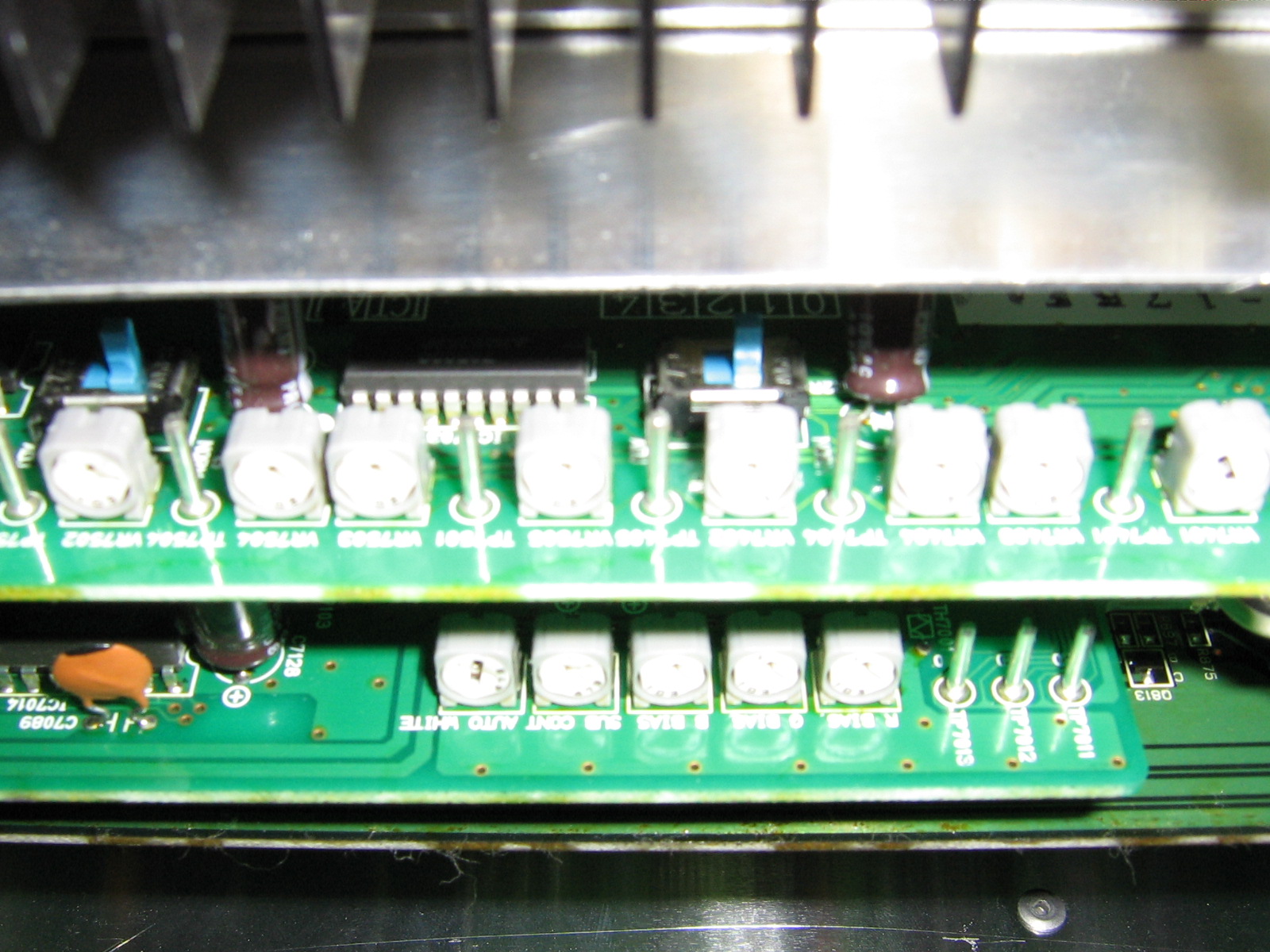
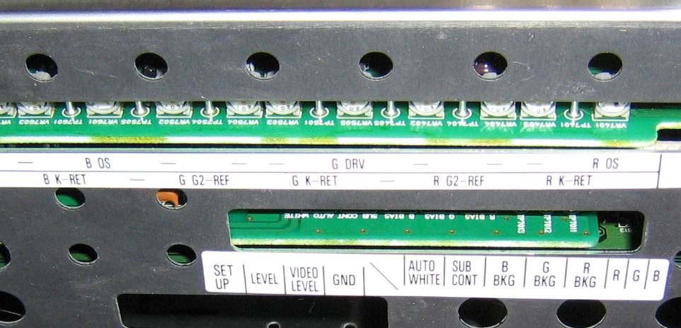
The procedure seems to be referring to the pots on the 'Video Out' and 'Gain CTL' boards however neither the card cage labeling nor the silk-screened text on the cards agree with what's called out in the procedure. The G2 test points and AKB Test switch (in the procedure) are located on the 'Video Out' card.
Standing under the lenses (ceiling mounted) and looking rearward, the Video Out card pots and test points are arranged as depicted in the attached photos and attached text doc. (The layouts were attached as a text file because the posting editor automatically justifies out the spacebars). In the layout text file, the period symbol denotes a Test Point and the X denotes a potentiometer (sorry, it's not easy to draw with text). TP7xxx or VR7xxx is the text that is silk-screened on the circuit board below each component. The G2 test points are identified in the procedure text and the card cage labeling. You should see that they logically arrange and repeat into three groups for Blu, Grn and Red.
Directly above each group of pots and test points is a slide switch, not identified in the procedure text, with 'Adj' and 'Norm' positions silk-screened on the card. Whether it means anything or not, the switches are directly above the G2 test points in each logical section.
Each of the G2 test points (TP7604, 7504, 7404) appears to have a companion potentiometer (VR7604, 7504, 7404).
Not necessarily related to the G2 prcedure, notice that there is a Blue TP7605 and a companion VR7605. Similarly, there is a Red TP7401 and a companion VR7401. The Grn TP7501 has a companion VR7505. It's just curious that NEC didn't use the same labeling method unless it does something different than the other two sections. The service manual will tell.
The layout of the 'Gain CTL' card was left here to demonstrate how the post editor strips out additional spacebars from the text. Refer to the attached layout text file.
X X X X X . . .
| | | | | | | |
| | | | | | | |
Auto Sub B G R TP TP TP
White Cont Bias Bias Bias 7013 7012 7011
So here's the procedure mentioned at the top of this post. My comments, questions or observations are appended in red.
{start procedure}
Steps:
1) Allow 30 min warm up.
2) Turn color saturation in your video processing all the way down, otherwise grayscale can be thrown off by several hundred degrees.
3) Set your processor to a minimum of line doubling, your can use anything above that also. Does this step make sense to anyone?
4) If your processor has brightness and contrast control set them to default.
5) Turn "Blue Focus Tracking" off...display focus pattern and adjust for sharpest focus, then turn "Blue Focus Tracking" back on. (This insures correct amount of projector defocusing) . Blue Focus Tracking is menu selected in Adjust... Option... Setting Mode... scroll to B Focus Tracking
6) Set all "Kelvin" adjustments to default (50, both Black & White). The Kelvin menu has two selections: Color Temp and White Balance. Temp is a sliding scale from 3200 to 9500 so middle-of-the-road might be 6300K but more likely is 6500K. The White Balance menu allows black and white levels to be adjusted for each CRT so this may be the menu referred to in this step. The NEC user setup manual only refers to these adjustments while viewing a 100IRE window. It does not describe what the end result to be obtained should be.
7) Open "Blanking" to max in all directions.
8) Set "Brightness" to 60.
9) Set "Contrast" to show 100ire window at normal level for your system (default?). I don't know what end result is desired for this step, nor what the normal or default level is.
10) Set "AKB" test switch to test position.
11) Set your DMM (digital multimeter) to VDC and measure test points TP7404 (red G2) TP 7504 (green G2) and 7604 (blue G2) verify the voltage is 2.5 vdc +/-0.1 vdc...if not try small adjustments of "Contrast", if that doesn't help, call a service tech. In my case, all G2's are 2.5V, +/- 0.1V. However, changing 'contrast' makes no change to any G2 voltage. Should it???
12) Adjust Black Bias to 50 (default) this is just a "rough setting". Where is Black Bias? This control is also called out in the loop-step 'B' which follows. It implies an NEC menu selection and setting it's sliding scale to the middle. I know of no such menu selection on my system (XG-1350). Or, if it's not a menu selection, where's the control and set it to 50-what?
13) Set "AKB" test switch back to Normal position.
14) Display AVIA "Verical Crossed Gray Ramp" pattern.
Note: Now begins the "adjustment loop" which you must repeat until G2 voltages no longer deviate from 2.5 vdc then readjusting and re-measuring during changes in the upcoming adjustments.
A) Begin Green Loop:
B) Adjust "Black Bias" to make TP7504 (GRN) read 2.5 vdc +/ 0.1vdc. Which pot is Black Bias?
C) Look into the Green tube & see Gray ramps going vertically in opposite directions. Pay close attention to the dark edges of either ramp. Set "Bright Bias" to a point that just makes the dark outer edges of the ramps go black...the idea is to make the smallest amount of the ramp go black, make sure some of the ramp DOES go black. Which pot is Bright Bias?
D) Set "Brightness" to 0.
E) Look into the Green lens, you will now see a much darker looking ramp. Look at the edge of the ramp that goes from light to dark...Adjust "Bright Gain" to make the black edges of the ramps just meet at the center. Which pot is Bright Gain?
F) Set "Brightness" back to 60.
G) IF Green G2 still reads 2.5 vdc +/- 0.1 then exit Green adjustment loop...otherwise restart adjustment loop at step "B" (it's a good idea to run through this a second time anyway).
16) Begin Red adjustment loop, repeat steps B thru G.
17) Repeat steps B thru G for Blue gun.
18) From this point on, DO NOT adjust any of the Green gun's settings in the "White Ref" menu...this gun will serve as a reference by which Red & Blue guns are fine tuned for grayscale. Is this step refering to the 'Ref White Bal' menu selection (Adjust... Ref Adj... Ref White Bal)? This is a Service Personnel Only selection. I don't know the magic to select this menu. Furthermore, if we were in that menu, which step put us there in the first place?
19) Calibrate grayscale using "Drive Control" for 100 ire window, and "Bright Bias" for the low end (30 ire) note that it will take several adjustment loops to get a flat grayscale, as these adjustment are dependent on each other. Which pot is Drive Control? Which pot is Bright Bias? Or are we in the White Ref menu from the previous step?
20) Since you have probably had to change the G2 calibrated Red & Blue "Bright Bias" setting to get Red & Blue guns to track with the Green you must check your TP voltages again, if they are not at 2.5 vdc readjust "Black Bias" to get proper voltage. Is this step also refering to the Service Only Ref White Bal menu?
21) Verify that "AKB" test switch makes only minor changes in screen appearance.
22) Readjust Brightness, Contrast & Kelvin for each memory slot.
Your done!
{end procedure}
| Description: |
| Card Cage removed, cards exposed |
|
| Filesize: |
461.91 KB |
| Viewed: |
37 Time(s) |
|
| Description: |
|
| Filesize: |
71.04 KB |
| Viewed: |
96 Time(s) |
|
| Description: |
| Text file depicting test point and potentiometer layouts on the NEC-XG Video Out and Gain CTL cards. |
|

Download |
| Filename: |
Layout.txt |
| Filesize: |
1.4 KB |
| Downloaded: |
16 Time(s) |
_________________
Mumz
|
|
| Back to top |
|
 |
Mr. Green

Joined: 23 Feb 2007
Posts: 1394
Location: Calgary
TV/Projector: Marquee 9501LC / NEC 9PG+
|
| Posted: Sun Dec 27, 2009 11:23 pm Post subject: |
|
|
I give it 3 posts before someone tells you not to touch it... 
_________________
You can be young only once but, you can be immature forever.
Current Projector Marquee9501LC with PS3 (BLu-Ray) at 1080P LOVE IT! Screen is an Elunevision 120" 4:3 (2.4 gain - no hotspots). (also own a NEC 9PG+)
|
|
| Back to top |
|
|
Curt Palme
CRT Tech
Joined: 08 Mar 2006
Posts: 24396
Location: Langley, BC
TV/Projector: All of them!
|
| Posted: Mon Dec 28, 2009 2:13 am Post subject: Re: NEC-XG G2 Adjustment Procedure |
|
|
| Don Mummey wrote: |
{start procedure}
Steps:
1) Allow 30 min warm up.
2) Turn color saturation in your video processing all the way down, otherwise grayscale can be thrown off by several hundred degrees.
3) Set your processor to a minimum of line doubling, your can use anything above that also. Does this step make sense to anyone? Yes, any resolution above 480p can be used.
4) If your processor has brightness and contrast control set them to default.
5) Turn "Blue Focus Tracking" off...display focus pattern and adjust for sharpest focus, then turn "Blue Focus Tracking" back on. (This insures correct amount of projector defocusing) . Blue Focus Tracking is menu selected in Adjust... Option... Setting Mode... scroll to B Focus Tracking
6) Set all "Kelvin" adjustments to default (50, both Black & White). The Kelvin menu has two selections: Color Temp and White Balance. Temp is a sliding scale from 3200 to 9500 so middle-of-the-road might be 6300K but more likely is 6500K. The White Balance menu allows black and white levels to be adjusted for each CRT so this may be the menu referred to in this step. The NEC user setup manual only refers to these adjustments while viewing a 100IRE window. It does not describe what the end result to be obtained should be. Nothing. Set them all to midposition. If your color balance/tracking is off, you won't get a white window here, which is why you're asking to adjust this in the first place. 
7) Open "Blanking" to max in all directions.
8) Set "Brightness" to 60.
9) Set "Contrast" to show 100ire window at normal level for your system (default?). I don't know what end result is desired for this step, nor what the normal or default level is. I always use 60 brightness and 75 contrast, the NEC default settings.
10) Set "AKB" test switch to test position.
11) Set your DMM (digital multimeter) to VDC and measure test points TP7404 (red G2) TP 7504 (green G2) and 7604 (blue G2) verify the voltage is 2.5 vdc +/-0.1 vdc...if not try small adjustments of "Contrast", if that doesn't help, call a service tech. In my case, all G2's are 2.5V, +/- 0.1V. However, changing 'contrast' makes no change to any G2 voltage. Should it??? No, I've never had a case where the 'test' position is anything other than 2.5 volts. If it is, I'd guess you have a problem on one of the video boards.
12) Adjust Black Bias to 50 (default) this is just a "rough setting". Where is Black Bias? This control is also called out in the loop-step 'B' which follows. It implies an NEC menu selection and setting it's sliding scale to the middle. I know of no such menu selection on my system (XG-1350). Or, if it's not a menu selection, where's the control and set it to 50-what? It is in a hidden menu. See my other post about that.
13) Set "AKB" test switch back to Normal position.
14) Display AVIA "Verical Crossed Gray Ramp" pattern.
Note: Now begins the "adjustment loop" which you must repeat until G2 voltages no longer deviate from 2.5 vdc then readjusting and re-measuring during changes in the upcoming adjustments.
A) Begin Green Loop:
B) Adjust "Black Bias" to make TP7504 (GRN) read 2.5 vdc +/ 0.1vdc. Which pot is Black Bias? These and the others below are accessed via the remote.
C) Look into the Green tube & see Gray ramps going vertically in opposite directions. Pay close attention to the dark edges of either ramp. Set "Bright Bias" to a point that just makes the dark outer edges of the ramps go black...the idea is to make the smallest amount of the ramp go black, make sure some of the ramp DOES go black. Which pot is Bright Bias?
D) Set "Brightness" to 0.
E) Look into the Green lens, you will now see a much darker looking ramp. Look at the edge of the ramp that goes from light to dark...Adjust "Bright Gain" to make the black edges of the ramps just meet at the center. Which pot is Bright Gain?
F) Set "Brightness" back to 60.
G) IF Green G2 still reads 2.5 vdc +/- 0.1 then exit Green adjustment loop...otherwise restart adjustment loop at step "B" (it's a good idea to run through this a second time anyway).
16) Begin Red adjustment loop, repeat steps B thru G.
17) Repeat steps B thru G for Blue gun.
18) From this point on, DO NOT adjust any of the Green gun's settings in the "White Ref" menu...this gun will serve as a reference by which Red & Blue guns are fine tuned for grayscale. Is this step refering to the 'Ref White Bal' menu selection (Adjust... Ref Adj... Ref White Bal)? This is a Service Personnel Only selection. I don't know the magic to select this menu. Furthermore, if we were in that menu, which step put us there in the first place?
19) Calibrate grayscale using "Drive Control" for 100 ire window, and "Bright Bias" for the low end (30 ire) note that it will take several adjustment loops to get a flat grayscale, as these adjustment are dependent on each other. Which pot is Drive Control? Which pot is Bright Bias? Or are we in the White Ref menu from the previous step?
20) Since you have probably had to change the G2 calibrated Red & Blue "Bright Bias" setting to get Red & Blue guns to track with the Green you must check your TP voltages again, if they are not at 2.5 vdc readjust "Black Bias" to get proper voltage. Is this step also refering to the Service Only Ref White Bal menu?
21) Verify that "AKB" test switch makes only minor changes in screen appearance.
22) Readjust Brightness, Contrast & Kelvin for each memory slot.
Your done!
{end procedure} |
OK a few things. None of the pots on either of those boards should be touched. All this is done in the menus, under the 'reference' section.
I've clarified the above in blue. Hopefully.
|
|
| Back to top |
|
|
Zebu Fellenz
Joined: 21 Dec 2006
Posts: 2567
|
| Posted: Mon Dec 28, 2009 2:17 am Post subject: |
|
|
| Mr. Green wrote: | | I give it 3 posts before someone tells you not to touch it... |
Not even that many.
Is there a problem with G2? I've heard many times that the XG can be messed up very badly by misadjustment in the white balance and I believe also G2.
If it's not broke don't try to fix it.
-Edit, Curt beat me to it, adjust with the remote, keep your hands off those pots. 
|
|
| Back to top |
|
|
Curt Palme
CRT Tech
Joined: 08 Mar 2006
Posts: 24396
Location: Langley, BC
TV/Projector: All of them!
|
| Posted: Mon Dec 28, 2009 2:21 am Post subject: |
|
|
Let me add Don, WHY do you want to do this? Generally speaking, unless you've changed system cards, the XG is pretty self adjusting. If your color balance is off, you probably have a board problem somewhere, tubes are badly worn, in which case they need changing. Rare is the case (I can't recall one) that you need into the super secret area unless you've changed tubes or system boards.
See my further post to this over in the CRT projector forum.
|
|
| Back to top |
|
|
|
|
|
|
|
You cannot post new topics in this forum
You cannot reply to topics in this forum
You cannot edit your posts in this forum
You cannot delete your posts in this forum
You cannot vote in polls in this forum
You cannot attach files in this forum
You can download files in this forum
|
Forum powered by phpBB © phpBB Group
|
|


