| Author |
Message |
HD-DAVE

Joined: 16 Feb 2007
Posts: 225
Location: Delta, BC
|
| Posted: Thu Jun 11, 2009 6:56 pm Post subject: Dead $25,000 Pioneer Plasma - what am I in for ? |
|
|
Hey, I just obtained a PDP-501MX for free - has the distinction of being the first real hi-def plasma ever... a whopping $25K new back in '99 ( don't worry I haven't gone over to the dark side, my Nec XG is still king).
Has anyone ever dealt with PD issues for one of these beasts ? It shuts down after 2 secs - builds Vsus ok, all other voltages I've checked so far look ok - nothing burnt looking. I was lucky enough to get the service manual from a russian website ( Спасибо !!! Dos vedanya comrades! ) so now I am pouring over unbelievably complicated power supply schematics. Wee! 
Any repair stories/advice appreciated !
...Dave
|
|
| Back to top |
|
 |
Nashou66

Joined: 12 Jan 2007
Posts: 16171
Location: West Seneca NY
|
|
| Back to top |
|
|
macgyver655
Joined: 22 Aug 2007
Posts: 8508
|
| Posted: Thu Jun 11, 2009 9:03 pm Post subject: |
|
|
Well lets see. From the info I have, these displays had problems with the power supply and the scan B boards. The power supply problems were so bad that Pioneer was extending the warranty on them.
There are 4 scan B boards mounted along the outside edge. They are about 3 X 5 inches. You can try disconnecting them 1 at a time and see if the display stays on.
That manual you have has schematics? From what I heard Pioneer didn't release the diagrams on that unit. If it does then I wouldn't mind having a copy of it....... 
|
|
| Back to top |
|
|
Curt Palme
CRT Tech
Joined: 08 Mar 2006
Posts: 24396
Location: Langley, BC
TV/Projector: All of them!
|
| Posted: Thu Jun 11, 2009 10:20 pm Post subject: |
|
|
THe fact that he's a stone's throw from me and I didn't catch wind of this find ticks me off.
Heehee! 
Great score! I'd love to keep track of this repair. I've only ever popped the back off one plasma, an LG, and sent it out for repairs.
Cheers!
|
|
| Back to top |
|
|
HD-DAVE
Joined: 16 Feb 2007
Posts: 225
Location: Delta, BC
|
| Posted: Fri Jun 12, 2009 6:26 pm Post subject: |
|
|
Thanks for the replies so far...and Sorry Curt but this one wasn't public like a craiglist ad or anything. I bought my XG from u if that's any consolation !!! 
Well in the limited time I had last night checking PD feeds into the PSU I have it narrowed down to the Y-Drive A assembly. Luckily the service manual has a PD troubleshooting block diagram page however component ID'ing is time consuming....biggest problem I have is the service manual does not have very detailed board overlays for the video / cpu boards which show every last test point (it does show some and has a decent one for the PSU at least) and my 40-something eyes have a hard time reading the microscopic silkscreened text for the components.
The PSU board in this is unbelievable ... biggest board I have ever worked on bar none. Weighs about 5 pounds all by itself ! so many points of failure...
MacG the service manual only has PSU schematic - nothing else. All the rest is either interconnect lists or block diagrams of the set and specific IC's. I have a PDF of the service manual if you want me to email it to you send me your addy.
HD-Dave
|
|
| Back to top |
|
|
Curt Palme
CRT Tech
Joined: 08 Mar 2006
Posts: 24396
Location: Langley, BC
TV/Projector: All of them!
|
| Posted: Fri Jun 12, 2009 8:25 pm Post subject: |
|
|
I'm just giving you a hard time.
Good score indeed.
|
|
| Back to top |
|
|
HD-DAVE
Joined: 16 Feb 2007
Posts: 225
Location: Delta, BC
|
| Posted: Mon Jun 15, 2009 3:40 pm Post subject: |
|
|
More progress...something is pulling down (possibly shorting) the VH_A (150V), or there is a VH_A generation fault. VH_A is derived from one of the Sustain supply voltages (~175VDC) via a DC-DC converter, and there is also a secondary 5 VDC supply that is not being generated...could either be bad DC-DC converter or possibly even a scan IC fault. Doing the basics right now looking for high ESR caps, getting spec sheets online for the DC-DC converter components...
Later!
Dave
|
|
| Back to top |
|
|
macgyver655
Joined: 22 Aug 2007
Posts: 8508
|
| Posted: Mon Jun 15, 2009 3:58 pm Post subject: |
|
|
| HD-DAVE wrote: | More progress...something is pulling down (possibly shorting) the VH_A (150V), or there is a VH_A generation fault. VH_A is derived from one of the Sustain supply voltages (~175VDC) via a DC-DC converter, and there is also a secondary 5 VDC supply that is not being generated...could either be bad DC-DC converter or possibly even a scan IC fault. Doing the basics right now looking for high ESR caps, getting spec sheets online for the DC-DC converter components...
Later!
Dave |
The scan ic's are on those scan B boards I suggested to disconnect to see if it would start up. Its a common problem with that display.
|
|
| Back to top |
|
|
HD-DAVE
Joined: 16 Feb 2007
Posts: 225
Location: Delta, BC
|
| Posted: Tue Jun 16, 2009 7:46 pm Post subject: |
|
|
Mac you were on the money - VH is being shorted by the Scan A board somewhere... I unplugged its micro ribbon cable and the power supply fires up now. I am also getting a partial image  - a white-ish band across the top of the screen. In your experience is this normal or should more of the screen come up ? ... Oh, I think I just figured it out I bet there should be no "raster" on this top part. Probably should be all dark with some coloured text for input source and what-not. - a white-ish band across the top of the screen. In your experience is this normal or should more of the screen come up ? ... Oh, I think I just figured it out I bet there should be no "raster" on this top part. Probably should be all dark with some coloured text for input source and what-not.
As for Scan A board I'll do some testing on the discretes and may check the 3 individual IC's but if they are dead I'm not expecting to be able to do much more than a board replacement since the scan IC is long ago discontinued...I don't have the soldering gear to do surface mount this fine even if I did have the chip.
Thanks ....Dave
|
|
| Back to top |
|
|
macgyver655
Joined: 22 Aug 2007
Posts: 8508
|
| Posted: Tue Jun 16, 2009 8:20 pm Post subject: |
|
|
Yes, partial image is what you will get. What you have to remember is that a bad display can cause the board failure. You may replace the board only to find that display is bad.
Are there 3 other boards in there that look just like that one?
|
|
| Back to top |
|
|
macgyver655
Joined: 22 Aug 2007
Posts: 8508
|
| Posted: Tue Jun 16, 2009 8:49 pm Post subject: |
|
|
|
Is the number on those scan ic's SN755862PJA ?
|
|
| Back to top |
|
|
HD-DAVE
Joined: 16 Feb 2007
Posts: 225
Location: Delta, BC
|
| Posted: Tue Jun 16, 2009 10:03 pm Post subject: |
|
|
|
Yes, there are three others...Scan A, B, C, D. All have the Texas Instruments SN755862PJA. Is it safe to try trading the identically numbered Scan boards around to see if its the display is bad ? ... Dave
|
|
| Back to top |
|
|
macgyver655
Joined: 22 Aug 2007
Posts: 8508
|
| Posted: Tue Jun 16, 2009 11:34 pm Post subject: |
|
|
| HD-DAVE wrote: | | Yes, there are three others...Scan A, B, C, D. All have the Texas Instruments SN755862PJA. Is it safe to try trading the identically numbered Scan boards around to see if its the display is bad ? ... Dave |
Yes, swap them around and see if the section of the display that is not working with the bad board disconnected will work with a different one.
|
|
| Back to top |
|
|
HD-DAVE
Joined: 16 Feb 2007
Posts: 225
Location: Delta, BC
|
| Posted: Wed Jun 17, 2009 3:42 pm Post subject: |
|
|
|
All I had time for last night was a quick diode test on the pair of FETs on the Scan A ... both show possibly shorted compared to the supposedly good ones on the other scan boards - I'll pull them out tonight and test out of circuit. Or maybe try the Scan board switcheroo if I feel ambitious...however I'd rather carry on with component testing and not mess too much with those fine ribbon cables/connectors. Unplugging and reconnecting these repeatedly could lead to intermittants down the road
|
|
| Back to top |
|
|
macgyver655
Joined: 22 Aug 2007
Posts: 8508
|
|
| Back to top |
|
|
HD-DAVE
Joined: 16 Feb 2007
Posts: 225
Location: Delta, BC
|
| Posted: Wed Jun 17, 2009 4:34 pm Post subject: |
|
|
|
Thanks, Mac. I did anticipate the those FETs are connected to the scan IC's and probably all it takes is one bad driver inside any of the three scan IC's to mess with the in-circuit measurement at the FETs. I did see the two scan boards for $25 clams on ebay. First thing tonight when I get home will be to swap the Scan C board for the scan A and if the display is ok I will buy both of them...
|
|
| Back to top |
|
|
HD-DAVE
Joined: 16 Feb 2007
Posts: 225
Location: Delta, BC
|
| Posted: Thu Jun 18, 2009 2:40 am Post subject: |
|
|
WOO HOOOOOO! ... Houston we have a functional panel ! Tried the Scan C board in the "Scan A" position and it didn't blow up. In fact I saw a 3/4's image - only missing the 1/4 height horizontal band of pixels where the Scan C board was pulled out of for testing... was able to see some fine looking pixels after pushing the Menu button.
The board in Scan C position was actually silkscreened as a Scan A so I had two Scan A's, a Scan C and Scan D in the set, and not in the correct order top to bottom either --- hmm I think some previous service might have been done ?
Anyways, I did the BIN on the Scan A on Ebay so i'll have it within a week or so. Thanks for the tips, Mac!
|
|
| Back to top |
|
|
macgyver655
Joined: 22 Aug 2007
Posts: 8508
|
| Posted: Thu Jun 18, 2009 1:41 pm Post subject: |
|
|
|
Sure thing.... Wont it be nice to have a working plasma for around 30 bucks........
|
|
| Back to top |
|
|
HD-DAVE
Joined: 16 Feb 2007
Posts: 225
Location: Delta, BC
|
| Posted: Wed Nov 11, 2009 6:46 pm Post subject: |
|
|
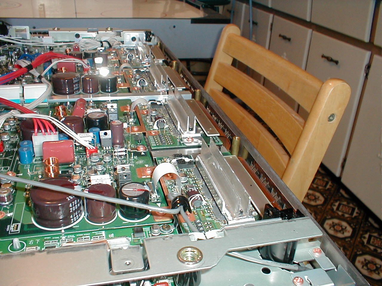
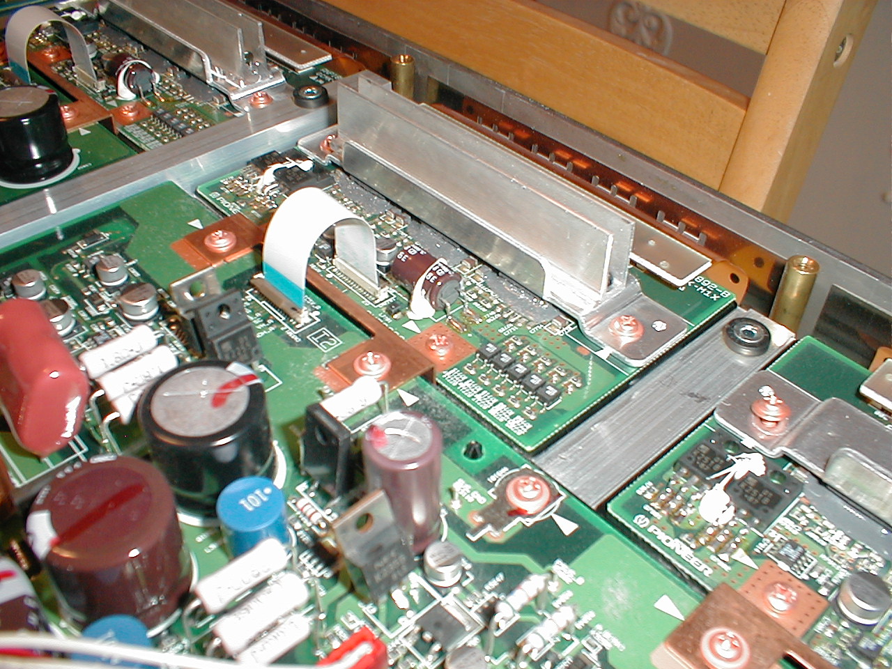
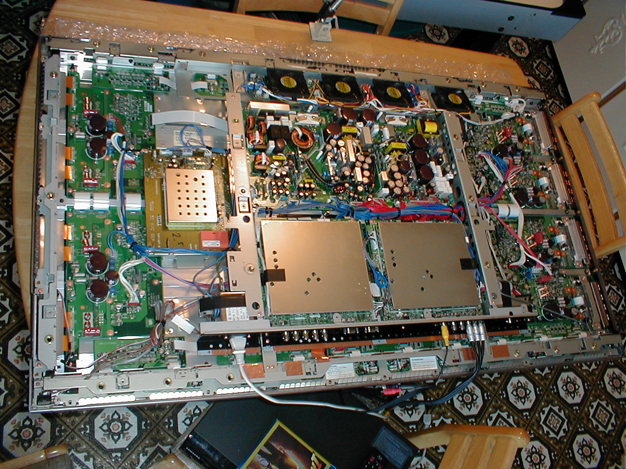
Hey guys & girls, so much going on over the past two months, I never had a chance to update this thread: the good news is my free "vintage" Plasma is still humming along nicely. Once in awhile there is a slight greenish edge tint on the "trailing edge" of fast moving objects, which disappears once movement stops, but after awhile my brain tunes it out. Perhaps this is a "plasma characteristic" ? What I did want to mention was my cooling upgrade to the SCAN boards: I noticed these boards (4) got pretty darn warm after a 1/2 hr or more of operatiion, and only have a thin flat piece of aluminum overtop the three IC's per board. What I did was take some large power supply heatsink fin assemblies and custom cut them to bolt onto the existing heat sink. Here are some photos.... I highly recommend this, I think it will extend the life of these crucial components in the set.
| Description: |
|
| Filesize: |
371.53 KB |
| Viewed: |
95 Time(s) |
|
| Description: |
|
| Filesize: |
392.94 KB |
| Viewed: |
92 Time(s) |
|
| Description: |
|
| Filesize: |
397.16 KB |
| Viewed: |
87 Time(s) |
|
|
|
| Back to top |
|
|
AnalogRocks
Forum Moderator
Joined: 08 Mar 2006
Posts: 26706
Location: Toronto, Ontario, Canada
TV/Projector: Sony 1252Q, AMPRO 4000G
|
| Posted: Wed Nov 11, 2009 11:57 pm Post subject: |
|
|
Nicely done.
_________________
Tech support for nothing
CRT.
HD done right!
|
|
| Back to top |
|
|
|
|


