| Author |
Message |
garyfritz

Joined: 08 Apr 2006
Posts: 12088
Location: Fort Collins, CO
|
| Posted: Mon May 04, 2009 8:34 pm Post subject: Marquee problems after faint-line mod |
|
|
I finally got around to doing the faint-line mod on my 8500. It had always had a faint line about 1/4 of the way from the right side, and it also had a squarish area in the center of the raster (top-to-bottom, but extended from the faint line on the right side to about 1/4 from the left side) that was a bit brighter than the raster on either side.
After doing the mod, I have a few problems:
* I lost my blue!! I checked the video cable on the VIM and it seems to be seated well. The mod is nowhere near the blue video jack but who knows where the blue signal runs...
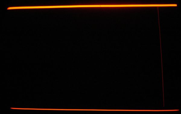
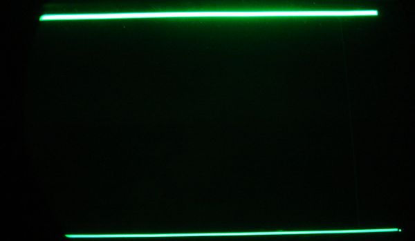
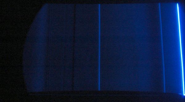
* Blue has a bright bar at the right side of the raster. Red & Green have bright bars on top & bottom. See pix.
* Blue also has some significant irregularities on the raster. See pic (gamma enhanced to bring out the detail).
I think the brighter squarish area is gone, but ironically the faint line is still there on R & G (!?) though it seems to be dim enough that I don't notice it on-screen. You can just see it on the red picture, but it's very faint on the green picture. I'm not sure but it might be closer to the right edge than it was before.
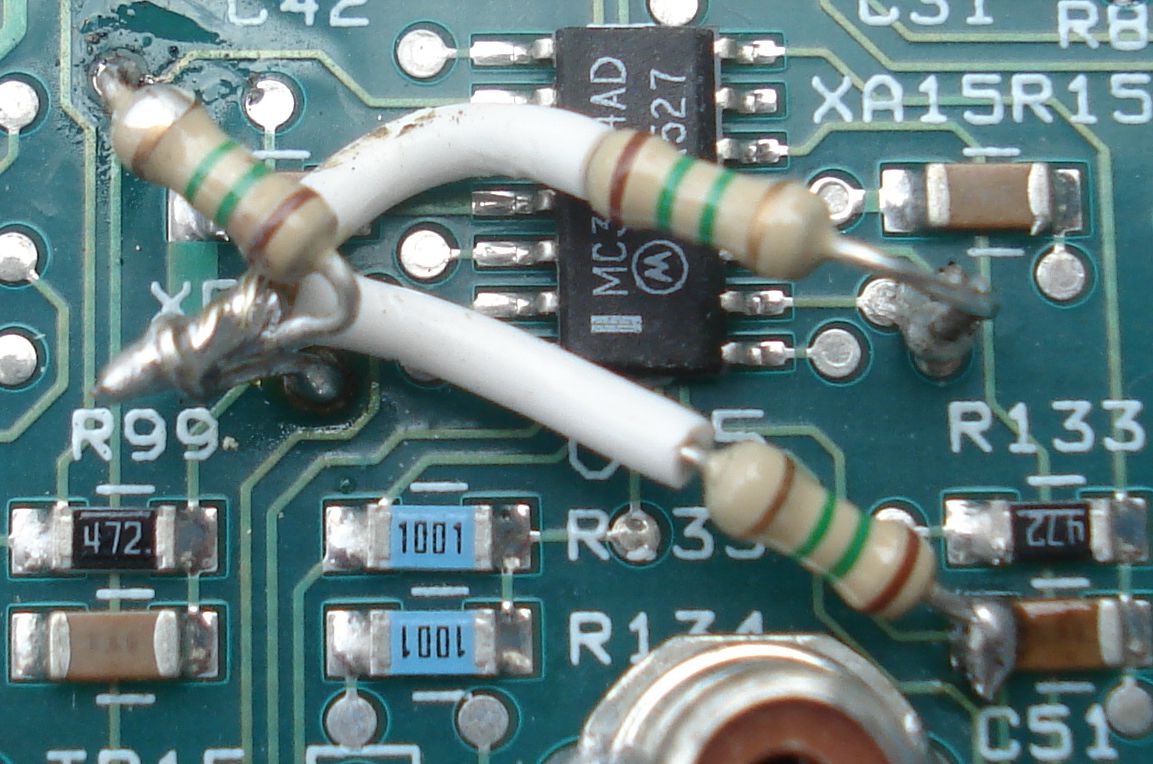
Looking at the picture of the mod (sorry for my messy soldering  ), I see a bit of splash-over at the upper left, but I doubt that's it. But the connection on the right doesn't look so good. I checked the back of the board and I'm definitely in the right thru-hole, but I think a glob of solder on the wire shorted pins 9 and 10 together. Testing on the back shows 9 and 10 are definitely shorted. Any guesses if that would cause the problems I'm seeing? I'm not going to mess with it any more until I get some opinions from people who know this stuff better than me. ), I see a bit of splash-over at the upper left, but I doubt that's it. But the connection on the right doesn't look so good. I checked the back of the board and I'm definitely in the right thru-hole, but I think a glob of solder on the wire shorted pins 9 and 10 together. Testing on the back shows 9 and 10 are definitely shorted. Any guesses if that would cause the problems I'm seeing? I'm not going to mess with it any more until I get some opinions from people who know this stuff better than me.
Thanks,
Gary
| Description: |
|
| Filesize: |
17.3 KB |
| Viewed: |
8516 Time(s) |
|
| Description: |
|
| Filesize: |
18.46 KB |
| Viewed: |
8516 Time(s) |
|
| Description: |
|
| Filesize: |
29.42 KB |
| Viewed: |
8516 Time(s) |
|
| Description: |
|
| Filesize: |
151.43 KB |
| Viewed: |
6811 Time(s) |
|
|
|
| Back to top |
|
 |
garyfritz
Joined: 08 Apr 2006
Posts: 12088
Location: Fort Collins, CO
|
| Posted: Mon May 04, 2009 9:38 pm Post subject: |
|
|
Couldn't wait. 
Sure enough, that was it. I cleaned off the excess solder, pulled the resistor and verified the two leads weren't shorted any more, put it back in & soldered it more carefully this time.
Now the faint line is still visible on the raster, but not on the screen at proper brightness levels. The blue raster seems OK now.
I still have the bright bars on top & bottom, though, on all 3 tubes now. Any guesses what's causing that?
|
|
| Back to top |
|
|
Nashou66

Joined: 12 Jan 2007
Posts: 16171
Location: West Seneca NY
|
| Posted: Mon May 04, 2009 9:44 pm Post subject: |
|
|
ok two problems i see ,
1) the solder joint from the through hole to pin 2 on u 15 should only be touching that through hole.
Looks like you have it also touching the through hole above the "R" in R133.
2) The intersection solder joint of the three resitors should only go to the trhough hole
point at the 2 O'clock position to R99 and not also to the 12 O'clock position through hole above R99.
It looks like you might have it connected to both.
So it looks like you have connected two through hole on both those points below the U15 chip. The one on the upper left looks ok.
here is My pic:

Athanasios
_________________
Don't blame your underwear for your crooked ass~ unknown Greek philosopher
"Republicans believe every day is the Fourth of July, but the Democrats believe every day is April 15." --- President Reagan
One Smart Dog!!!
Marquee High Performance Bellows now shipping!!
Marquee Modifications and Performance Enhancement
Marquee C-element and Bellow removal
|
|
| Back to top |
|
|
garyfritz
Joined: 08 Apr 2006
Posts: 12088
Location: Fort Collins, CO
|
| Posted: Mon May 04, 2009 9:57 pm Post subject: |
|
|
#1: Yes, you missed my response.
#2: No, where my picture shows the 3-resistor solder joint right above "R99," it's actually about 1/2" above the board. That's why it's out of focus. A single wire comes down from the joint to the 2 o'clock thru-hole, which you can see in the picture.
|
|
| Back to top |
|
|
Nashou66
Joined: 12 Jan 2007
Posts: 16171
Location: West Seneca NY
|
|
| Back to top |
|
|
garyfritz
Joined: 08 Apr 2006
Posts: 12088
Location: Fort Collins, CO
|
| Posted: Mon May 04, 2009 11:34 pm Post subject: |
|
|
|
I suppose it's possible... anybody got a clear idea what might cause those bars?
|
|
| Back to top |
|
|
garyfritz
Joined: 08 Apr 2006
Posts: 12088
Location: Fort Collins, CO
|
| Posted: Tue May 05, 2009 1:47 pm Post subject: |
|
|
OK, I dug up a data sheet for U15 and pulled out the schematic -- see pic.
Pins 9 and 10 are the inverting and non-inverting inputs of an op amp. The schematic shows them normally separated by a resistor and a capacitor, but I would think shorting them together would just result in no output from the op amp, with no damage to anything. And if it had damaged something, I would think it would only affect the red, since that op amp is used in the red channel -- see notation at upper right. There are equivalent circuits for green and blue, which use other op amps in U15. So unless I blew the whole U15 chip (which seems pretty unlikely), I would not expect any damage to affect all 3 channels. And if it did, would it manifest as top & bottom bars??? I have no idea. And why did shorting pins 9 & 10 (in the red channel) cause the blue bar to be on the right, with a messed-up raster!??
Somebody who can read a schematic a whole lot better than I can, would you see if you can guess what might cause those bars? Thanks!!
Gary
| Description: |
|
| Filesize: |
18.27 KB |
| Viewed: |
8429 Time(s) |
|
|
|
| Back to top |
|
|
Nashou66
Joined: 12 Jan 2007
Posts: 16171
Location: West Seneca NY
|
| Posted: Tue May 05, 2009 2:08 pm Post subject: |
|
|
Gary, you keep saying pins 9 and 10 but i think you mean pins 1 and 2 the white line on the one end of the chip , the line designates the side pin 1 in on, but just because the line is to the one side does not mean that is pin 1. look at XA15, that buffering cap is on the +15 rail which goes to pin 4. So pin 1 and 2 are the two pins you shorted which is the blue channel, also pin 1 is the output so you shorted it to pin 2. I am not sure if that would blow the chip but it might. if you coested the solder points and it is still acting up i'd change that chip.
Athanasios
_________________
Don't blame your underwear for your crooked ass~ unknown Greek philosopher
"Republicans believe every day is the Fourth of July, but the Democrats believe every day is April 15." --- President Reagan
One Smart Dog!!!
Marquee High Performance Bellows now shipping!!
Marquee Modifications and Performance Enhancement
Marquee C-element and Bellow removal
|
|
| Back to top |
|
|
garyfritz
Joined: 08 Apr 2006
Posts: 12088
Location: Fort Collins, CO
|
| Posted: Tue May 05, 2009 2:48 pm Post subject: |
|
|
Um. I think you're right that I had the chip backwards. But in that case I shorted 2 and 3, not 1 and 2. 2 and 3 are the +/- inputs to the blue op amp -- exactly the same inputs as 9 and 10 are for the red. So it makes sense that the blue went wonky, and was OK once I fixed the short.
But I still don't see how that causes the bars...
(No f'ing way am *I* changing that chip. I can't even put in a @%## resistor without f*cking it up...  ) )
|
|
| Back to top |
|
|
draganm

Joined: 08 Mar 2006
Posts: 8990
Location: Colorado
|
| Posted: Tue May 05, 2009 3:17 pm Post subject: |
|
|
Well in addition to all the bridged and shorted traces it looks like the solder connections were roasted, like the solder was heated beyone it's max temp. and cooked out.
| Quote: | UNACCEPTABLE -OVERHEATED SOLDER
Overheated solder has a dull, gray, frosty and/or crystallized appearance and is the result of excessive exposure to heat.
|
also, this is minor but
| Quote: | UNACCEPTABLE-FLUX RESIDUE
Flux residue indicates improper/ incomplete cleaning. |
I can try to repair that for you Gary but I can't promise you anything since it's not possible to tell what condition the board is in undeneath. As long as the traces on the board aren't jacked I can replace the amp and fix those solder joints
|
|
| Back to top |
|
|
garyfritz
Joined: 08 Apr 2006
Posts: 12088
Location: Fort Collins, CO
|
| Posted: Tue May 05, 2009 5:18 pm Post subject: |
|
|
It's sure possible I cooked the solder, though it's only a 40W iron. (Never heard of cooked solder causing a problem?) Would it be worth it to wick up that solder and re-solder the joints, or should I just touch the iron on them? If I understand right, the overheated solder only causes a problem because it boils and causes bubbles. I don't think it ruins the solder or anything. Reheating it should re-flow it properly.
I wonder if maybe I didn't get sufficient solder in some thru-hole so it connects to all layers properly? I would think the plating in the thru-hole should ensure proper contact to all layers if there's good contact on top or bottom.
I haven't done ANY cleaning, though, which is why you see the slop on that one joint. I guess I should get some denatured alcohol.
|
|
| Back to top |
|
|
WTS
Joined: 08 Mar 2006
Posts: 1276
Location: Calgary
|
| Posted: Tue May 05, 2009 6:01 pm Post subject: |
|
|
Suck it up and redo it properly, cold solder joints will come back to haunt you.
_________________
Thanks
Walter
|
|
| Back to top |
|
|
draganm
Joined: 08 Mar 2006
Posts: 8990
Location: Colorado
|
| Posted: Tue May 05, 2009 6:54 pm Post subject: |
|
|
| garyfritz wrote: | | It's sure possible I cooked the solder, though it's only a 40W iron. |
only a 40 watt iron? A 40 watt Iron can go to 900 degreees Farenheit which is 100 degrees above the max temp you should ever solder at. IMO, and FWIW, if you don't have an Iron with adjustable temp. dial it's not a good idea to even try this kind of work.
|
|
| Back to top |
|
|
Nashou66
Joined: 12 Jan 2007
Posts: 16171
Location: West Seneca NY
|
| Posted: Tue May 05, 2009 7:20 pm Post subject: |
|
|
| draganm wrote: | | garyfritz wrote: | | It's sure possible I cooked the solder, though it's only a 40W iron. |
only a 40 watt iron? A 40 watt Iron can go to 900 degreees Farenheit which is 100 degrees above the max temp you should ever solder at. IMO, and FWIW, if you don't have an Iron with adjustable temp. dial it's not a good idea to even try this kind of work. |
I agree, the first few upgrades i was doing in the Marquee thread I had the 15 or 30 watt adjustable and that wasn't even
useful for more than re-soldering . Then i got the Hot air and solder station with the vacuum and it was like night and day.
But bofore removing the chip remove all the mods and check the board. Hopefully it will work and you can try the mod one more time.
Athanasios
_________________
Don't blame your underwear for your crooked ass~ unknown Greek philosopher
"Republicans believe every day is the Fourth of July, but the Democrats believe every day is April 15." --- President Reagan
One Smart Dog!!!
Marquee High Performance Bellows now shipping!!
Marquee Modifications and Performance Enhancement
Marquee C-element and Bellow removal
|
|
| Back to top |
|
|
garyfritz
Joined: 08 Apr 2006
Posts: 12088
Location: Fort Collins, CO
|
| Posted: Tue May 05, 2009 9:54 pm Post subject: |
|
|
Hm. OK, the iron also runs at 20W. I'll use that from now on. I'm not likely to need a hot air station... I think??
I re-soldered the joints (with 20W) and checked it. The bars are still there but I **think** they're dimmer than they were?? Using the GetGray test disk, the bars are at about a 5% level. They're outside the picture area. At this point I almost think I could survive if I put up some velvet framing around the image.
But... I don't think it's the VIM! I'm using a PS3 as my source, running through a Moome EXT-HD to the 8500. I don't remember ever seeing these bars before -- 99.99% sure they weren't there. But I dug out my old Momitsu DVD player, feeding into Moome via a DVI->HDMI cable, and as far as I can see it DOES NOT show the bars! There's something else weird going on -- the signal out of the Momitsu is too bright, with a 0% window very visible, like a normal 10-15% level, even with BRIGHT at 0 !? It's been a long time since I had the Momitsu hooked up, basically ever since I got the Moome box, but I think I ran it through the Moome box for a while and I don't *think* it used to do that...
So: the bars seem to be associated with the PS3 ?? Something else is wrong too, since I'm not seeing BTB or WTW signals, and I'm sure I used to. *sigh* Better to check the PS3 settings again and see if I messed something up... and I'll dig up another video signal and see what that shows.
|
|
| Back to top |
|
|
garyfritz
Joined: 08 Apr 2006
Posts: 12088
Location: Fort Collins, CO
|
| Posted: Wed May 06, 2009 4:12 am Post subject: |
|
|
OK, it is definitely NOT the VIM. I hooked up my laptop directly to the 8500, no Moome box, and it looked beautiful. So either the PS3 or the Moome is introducing the bars. Don't ask me why they suddenly appeared after the mod.
It may be because the mod seems to have brightened things -- hence the bright Momitsu? I had to turn the BRIGHT way down for the laptop too. (But I don't think the PS3 was brighter??)
Have others who've done this dim-line mod noticed that the projector's low end is much brighter?
I think I'm going to have to recalibrate, and lower the G2's a bunch, to get decent darkness levels.
|
|
| Back to top |
|
|
garyfritz
Joined: 08 Apr 2006
Posts: 12088
Location: Fort Collins, CO
|
| Posted: Wed May 06, 2009 4:43 am Post subject: |
|
|
|
One last note tonight: I changed my PS3 settings (to the ones shown here) and now it seems to pretty much match my laptop. No visible bars, BTB and WTW are coming through, etc. Low end is now roughly as bright as the laptop & Momitsu. Not sure why I had the settings I had before, but these seem "better" ? I'll definitely need a recalibration.
|
|
| Back to top |
|
|
WTS
Joined: 08 Mar 2006
Posts: 1276
Location: Calgary
|
| Posted: Thu May 07, 2009 12:27 am Post subject: |
|
|
So are you ruling out the Moome unit?
_________________
Thanks
Walter
|
|
| Back to top |
|
|
garyfritz
Joined: 08 Apr 2006
Posts: 12088
Location: Fort Collins, CO
|
| Posted: Thu May 07, 2009 1:55 am Post subject: |
|
|
|
Yup, I'm pretty sure it was something with the PS3. Haven't quite figured out why the mod suddenly made it visible, but I think that's what happened. When I changed the PS3 settings, everything seems OK -- no bars. So it can't be the EXT-HD.
|
|
| Back to top |
|
|
WTS
Joined: 08 Mar 2006
Posts: 1276
Location: Calgary
|
| Posted: Thu May 07, 2009 2:04 am Post subject: |
|
|
Yes very odd.
_________________
Thanks
Walter
|
|
| Back to top |
|
|
|
|