| Author |
Message |
tse
Joined: 03 May 2006
Posts: 1014
Location: Sweatbucket, Fl.
|
| Posted: Wed Aug 03, 2011 12:05 am Post subject: |
|
|
Are you pulling the enable input high?
Scott
_________________
"Were we directed from Washington when to sow and when to reap, we would soon want bread."
Thomas Jefferson
|
|
| Back to top |
|
 |
dvh99
Joined: 25 Dec 2009
Posts: 2158
Location: nederland
|
| Posted: Wed Aug 03, 2011 8:16 am Post subject: |
|
|
scott on the marquee hdm pcb pin 1 (enable on uc3708n and nc on mc34151) they are tied to ground.
i lifted both legs but still no go.
does pin 1 need a 5 volt to not shutdown the outputs?
as you can see i didn`t pull enable high.
can i just connect pin1 to pin2?
_________________
1 answer always poses multiple questions.
marquee 9500ultra HD10L moome hdmi1.3 v3+ some mods.
|
|
| Back to top |
|
|
Nashou66

Joined: 12 Jan 2007
Posts: 16171
Location: West Seneca NY
|
|
| Back to top |
|
|
dvh99
Joined: 25 Dec 2009
Posts: 2158
Location: nederland
|
| Posted: Thu Aug 04, 2011 7:08 pm Post subject: |
|
|
it is not really clear to me to be honest.
nash what do you make of the datasheet?
the mc34151 are back in for now btw, they work ok with the voltage regulator.
_________________
1 answer always poses multiple questions.
marquee 9500ultra HD10L moome hdmi1.3 v3+ some mods.
|
|
| Back to top |
|
|
Nashou66
Joined: 12 Jan 2007
Posts: 16171
Location: West Seneca NY
|
| Posted: Thu Aug 04, 2011 7:44 pm Post subject: |
|
|
http://focus.ti.com/lit/ds/symlink/uc3708.pdf
Although each output can be activated independently with its own inputs, they can be forced low in common
through the action of either a digital high signal at the Shutdown terminal or by forcing the Enable terminal low.
The Shutdown terminal will only force the outputs low, it will not effect the behavior of the rest of the device. The
Enable terminal effectively places the device in under-voltage lockout, reducing power consumption by as much
as 90%. During under-voltage and disable (Enable terminal forced low) conditions, the outputs are held in a
self-biasing, low-voltage, state.
It says on the Texas instruments data sheet that it needs a 6.2 voltage High. its unclear to me if this sets the outputs to
the self biasing , low voltage state or not.
Wait i think it means if the enable is in a low voltage state it puts the outputs in the low voltage state. so try getting at least 6.2 volts to the enable switch, I guess you can use the voltage regulator you had with the right restores or zener diode to get to 6.2 volts.
Athanasios
_________________
Don't blame your underwear for your crooked ass~ unknown Greek philosopher
"Republicans believe every day is the Fourth of July, but the Democrats believe every day is April 15." --- President Reagan
One Smart Dog!!!
Marquee High Performance Bellows now shipping!!
Marquee Modifications and Performance Enhancement
Marquee C-element and Bellow removal
|
|
| Back to top |
|
|
dvh99
Joined: 25 Dec 2009
Posts: 2158
Location: nederland
|
| Posted: Fri Aug 05, 2011 2:53 am Post subject: |
|
|
i had 5 volts on it and thought it would suffice, apparantly this did not work.
i will try with 6.2volts from a lm317.
yes a low voltage shuts down the outputs, that was clear to me.
should have chosen the 3709, no enable pin to worry about.
_________________
1 answer always poses multiple questions.
marquee 9500ultra HD10L moome hdmi1.3 v3+ some mods.
|
|
| Back to top |
|
|
Nashou66
Joined: 12 Jan 2007
Posts: 16171
Location: West Seneca NY
|
|
| Back to top |
|
|
draganm

Joined: 08 Mar 2006
Posts: 8990
Location: Colorado
|
| Posted: Mon Nov 28, 2011 6:40 pm Post subject: |
|
|
| dvh99 wrote: | dragan here are the pics.

when i receive the uc3708n drivers the lm317 can be omitted.
update about this will follow. dennis |
One of the reasons I haven't tried this yet is because the final transistor choice for stepping down the 24VDC from the daughter board wasn't finalized yet.
| dvh99 wrote: | i had 5 volts on it and thought it would suffice, apparantly this did not work.
i will try with 6.2volts from a lm317. yes a low voltage shuts down the outputs, that was clear to me.
should have chosen the 3709, no enable pin to worry about. |
So Dennis what did you wind up doing? My understanding is that the uc3708 driver was supposed to deliver the correct voltage and no longer require the LM317. Did you try the 3709 or?
|
|
| Back to top |
|
|
dvh99
Joined: 25 Dec 2009
Posts: 2158
Location: nederland
|
| Posted: Tue Nov 29, 2011 8:39 am Post subject: |
|
|
no not yet.
since i didn`t have the 3709 at hand i reinstalled the original driver and it works fine ever since but i will surely try the 3709 any time soon.
_________________
1 answer always poses multiple questions.
marquee 9500ultra HD10L moome hdmi1.3 v3+ some mods.
|
|
| Back to top |
|
|
draganm
Joined: 08 Mar 2006
Posts: 8990
Location: Colorado
|
| Posted: Tue Nov 29, 2011 4:55 pm Post subject: |
|
|
| dvh99 wrote: | no not yet.
since i didn`t have the 3709 at hand i reinstalled the original driver and it works fine ever since but i will surely try the 3709 any time soon. |
Well I'm looking forward to it. A smaller parts count is always nice and should eliminate all the stuff on the top of the daughter board too?
I think this is one of the most impressive modifications ever done to a marquee, a real modification using modern parts and 21st century transistor technology. Way cool 
|
|
| Back to top |
|
|
draganm
Joined: 08 Mar 2006
Posts: 8990
Location: Colorado
|
| Posted: Sat Dec 03, 2011 8:19 pm Post subject: |
|
|
ok, spent the last hour looking at this closely and now I have a headache?  So the yellow wire which used to deliver 15 volts to the MC 31451P Mosfet driver is pulled up. If the driver itself is replaced with a 24VDC (or higher) rated driver . So the yellow wire which used to deliver 15 volts to the MC 31451P Mosfet driver is pulled up. If the driver itself is replaced with a 24VDC (or higher) rated driver .
Then we can run a jumper wire directly from the last pin on connector J11 to the yellow wire (splice).
The original MC 31451 is an inverting driver
http://search.digikey.com/us/en/products/MC34151PG/MC34151PGOS-ND/919081
Scott earlier suggested the CLA362 which is a non-inverting driver at $2. each. Is that an issue?
There is also a UC3709N at $7. each
http://search.digikey.com/scripts/DkSearch/dksus.dll?Detail&itemSeq=107880227&uq=634585172885203504
I would actually like to pull the 24VDC directly from the HDM main board and leave the Daughter board free, any foreseeable problems with that?
Parts list
2* cmf10120d
2* 6r8 (6.8 ohm) resistor 1/2 w
2* sbyv-27/100 or 200 volt or 1n4002
2* UC3709N Driver
1* 10uf 50volt electrolytic (back side)
1* 1uf 50 volt X7R ceramic
Obsolete:
(Voltage step down for old driver)
1* lt317 or lm317
1* 100nf/50v
1* 3k9 resistor 1/4w / 1/2w
1* 260r resistor 1/4w / 1/2w
Last edited by draganm on Wed Jan 04, 2012 4:24 am; edited 1 time in total
|
|
| Back to top |
|
|
dvh99
Joined: 25 Dec 2009
Posts: 2158
Location: nederland
|
| Posted: Sat Dec 03, 2011 11:40 pm Post subject: |
|
|
the cla part isn`t pin compatible with mc34151, the uc3709 is.
there are 2 driver mosfets to be replaced on the hdm, u12 and u1.
the 1 ohm resistor going to the vcc of 1ohm can be omitted too i guess, and simply jumpered.
_________________
1 answer always poses multiple questions.
marquee 9500ultra HD10L moome hdmi1.3 v3+ some mods.
|
|
| Back to top |
|
|
draganm
Joined: 08 Mar 2006
Posts: 8990
Location: Colorado
|
| Posted: Sun Dec 04, 2011 12:10 am Post subject: |
|
|
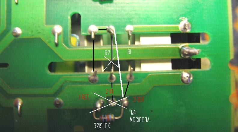
Ok, got an ever bigger headache now.  I was looking at the back of the actual PCB and noticed A couple of things I don't Reconcile with the drawing posted earlier. If we I was looking at the back of the actual PCB and noticed A couple of things I don't Reconcile with the drawing posted earlier. If we
1) take out Q4 and R2, and
2) by default R219 which is acting as a Return leg? then
3) jump-wire from the top of R2 to the through hole for the old "out" leg of Q4
Why do we need a Diode anywhere?
Black lines show traces on opposite side. Fat white line shows new jumper.
| Description: |
|
| Filesize: |
41.08 KB |
| Viewed: |
9317 Time(s) |
|
|
|
| Back to top |
|
|
draganm
Joined: 08 Mar 2006
Posts: 8990
Location: Colorado
|
| Posted: Sun Dec 04, 2011 12:15 am Post subject: |
|
|
| dvh99 wrote: | | the cla part isn`t pin compatible with mc34151, the uc3709 is. there are 2 driver mosfets to be replaced on the hdm, u12 and u1. |
No problem, $7. x 2 is only $14.
| dvh99 wrote: | | the 1 ohm resistor going to the vcc of 1ohm can be omitted too i guess, and simply jumpered. |
not sure what you mean, are you refering to the back-side of the HDM?
|
|
| Back to top |
|
|
Bodi79
Joined: 08 Oct 2011
Posts: 130
Location: Austria
|
| Posted: Sun Dec 04, 2011 12:59 am Post subject: |
|
|
@Nashou66
Thanx for your great Mods !
I already modded the focus board, vertical deflection board and the HVPS with your instructions so far.
Started to work on the CVA today , but at least here the images for the CVA are missing.
I managed mostly with the written instructions but it would be nice if i could look at it aswell 
Could you reupload them?
Thanx again
Ronald
|
|
| Back to top |
|
|
tse
Joined: 03 May 2006
Posts: 1014
Location: Sweatbucket, Fl.
|
| Posted: Sun Dec 04, 2011 1:08 am Post subject: |
|
|
It often helps to mark up a schematic to make sure everything is right.
IXDI604PI is a cheap high performance inverting (sorry about the non-inverting confusion) driver with the same pin-out as the original.
Scott
_________________
"Were we directed from Washington when to sow and when to reap, we would soon want bread."
Thomas Jefferson
|
|
| Back to top |
|
|
dvh99
Joined: 25 Dec 2009
Posts: 2158
Location: nederland
|
| Posted: Sun Dec 04, 2011 1:19 am Post subject: |
|
|
| draganm wrote: | Ok, got an ever bigger headache now. I was looking at the back of the actual PCB and noticed A couple of things I don't Reconcile with the drawing posted earlier. If we
1) take out Q4 and R2, and
2) by default R219 which is acting as a Return leg? then
3) jump-wire from the top of R2 to the through hole for the old "out" leg of Q4
Why do we need a Diode anywhere?
Black lines show traces on opposite side. Fat white line shows new jumper. |
you should jump wire q4 pin 2 and 3 (closest 2 holes to the heatsink) not from a resistor to a hole where a pin of q4 was.
the heatsink must be removed in order to get this modification done right.
diode is for voltage clamping this must be across the resistors on the bottom of the pcb (r219 and r220) with the minus side of the diode in the direction of the heatsink.
if you print out the schematic with the changes it will make it a lot easier.
_________________
1 answer always poses multiple questions.
marquee 9500ultra HD10L moome hdmi1.3 v3+ some mods.
|
|
| Back to top |
|
|
dvh99
Joined: 25 Dec 2009
Posts: 2158
Location: nederland
|
| Posted: Sun Dec 04, 2011 1:37 am Post subject: |
|
|
oops you`re right of course with the jumpering of r2 to pin3 of q4, i just jumpered the components i took out without giving it another look.
_________________
1 answer always poses multiple questions.
marquee 9500ultra HD10L moome hdmi1.3 v3+ some mods.
|
|
| Back to top |
|
|
draganm
Joined: 08 Mar 2006
Posts: 8990
Location: Colorado
|
| Posted: Sun Dec 04, 2011 1:47 am Post subject: |
|
|
Edited to make sense with previous post
| dvh99 wrote: | | if you print out the schematic with the changes it will make it a lot easier. |
I did print up your schEmAtic Dennis.
| dvh99 wrote: | | oops you`re right of course with the jumpering of r2 to pin3 of q4, i just jumpered the components i took out without giving it another look. |
thanks
| dvh99 wrote: | | the heatsink must be removed in order to get this modification done right. |
not a problem
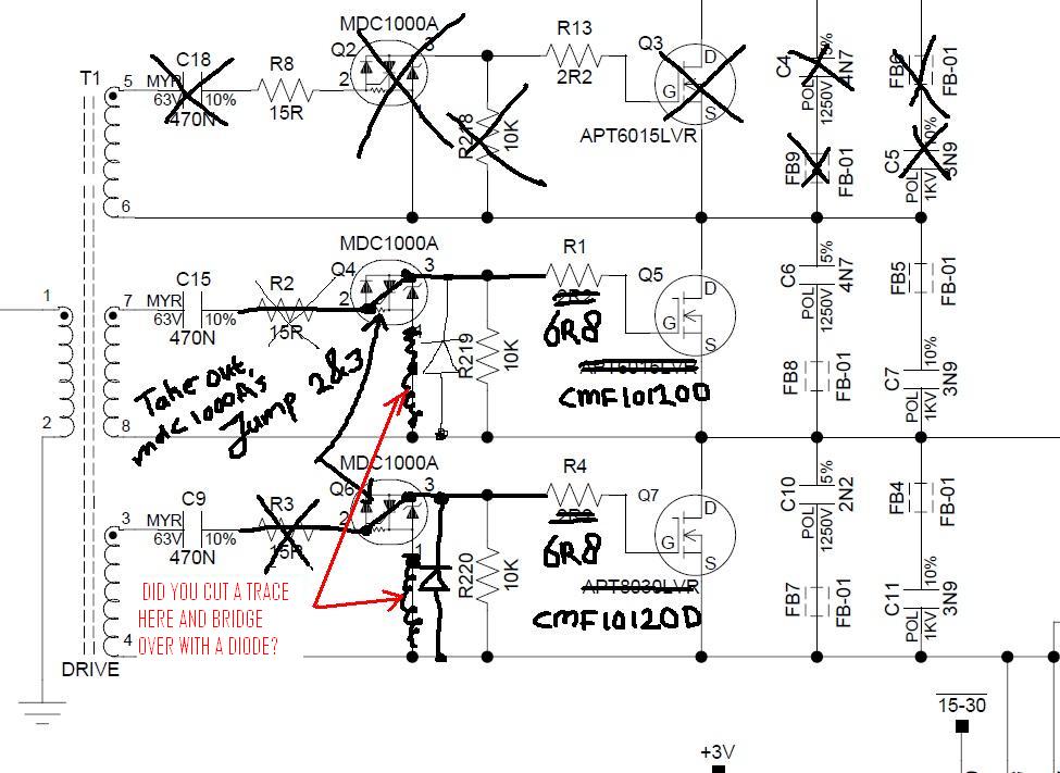
| dvh99 wrote: | diode is for voltage clamping this must be across the resistors on the bottom of the pcb (r219 and r220) with the minus side of the diode in the direction of the heat-sink.
if you print out the schematic with the changes it will make it a lot easier. |
leave R219 &220 in place and simply bridge over them with a Diode. got it !
the thing that's confusing is you show a trace cut on the board where you crossed out this line? Is this cut what your bridging with a Diode?
| Description: |
|
| Filesize: |
109.95 KB |
| Viewed: |
9272 Time(s) |
|
Last edited by draganm on Sun Dec 04, 2011 9:23 pm; edited 1 time in total
|
|
| Back to top |
|
|
Nashou66
Joined: 12 Jan 2007
Posts: 16171
Location: West Seneca NY
|
| Posted: Sun Dec 04, 2011 2:09 am Post subject: |
|
|
| Bodi79 wrote: | @Nashou66
Thanx for your great Mods !
I already modded the focus board, vertical deflection board and the HVPS with your instructions so far.
Started to work on the CVA today , but at least here the images for the CVA are missing.
I managed mostly with the written instructions but it would be nice if i could look at it aswell
Could you reupload them?
Thanx again
Ronald |
Ok Ronald fixed. I made a note about the 10uf caps as well.
In june apple mobile me gallery will be gone again so i will have to do this all over again!!
They keep upgrading but for me its a pain in the arse!
Athanasios
_________________
Don't blame your underwear for your crooked ass~ unknown Greek philosopher
"Republicans believe every day is the Fourth of July, but the Democrats believe every day is April 15." --- President Reagan
One Smart Dog!!!
Marquee High Performance Bellows now shipping!!
Marquee Modifications and Performance Enhancement
Marquee C-element and Bellow removal
|
|
| Back to top |
|
|
|
|


