| Author |
Message |
Nashou66

Joined: 12 Jan 2007
Posts: 16171
Location: West Seneca NY
|
| Posted: Sun Mar 17, 2013 8:16 pm Post subject: |
|
|
James regarding the CLM 47uf caps. make sure you get them in the right polarity or you'll pop a few. I still need to get those pics up.
I too wanted Os cons for the CLM but they do not make them that small and nothing will fit. If we went to oscons you could probably drop to 10-22uf values as Oscons filter better than a similar value of other caps.
I was thinking of trying a film SMT chip instead of the ceramics and Oscons since they are NP. Probably 1uf should be enough with a film cap. But I never found them at a decent price or smaller order amounts. But with these things its all trial and error.
For the VNB I am not sure what Drags uses or if He scoped the VNB afterwards. But I think Mike used in k range of pf.
Athanasios
_________________
Don't blame your underwear for your crooked ass~ unknown Greek philosopher
"Republicans believe every day is the Fourth of July, but the Democrats believe every day is April 15." --- President Reagan
One Smart Dog!!!
Marquee High Performance Bellows now shipping!!
Marquee Modifications and Performance Enhancement
Marquee C-element and Bellow removal
|
|
| Back to top |
|
 |
CxTurbo
Joined: 13 Oct 2008
Posts: 425
Location: Ontario, Canada
|
| Posted: Sun Mar 17, 2013 10:24 pm Post subject: |
|
|
I found a Cornell Dubilier 16V 1uF Film cap in a case size that is compatible with the "A" size 1206. The cost is not bad and in line with standard solid tantalum's and way less the the tantalum polymer.
http://ca.mouser.com/Search/ProductDetail.aspx?R=FCA1210C105M-G2virtualkey59850000virtualkey598-FCA1210C105M-G2
Data Sheet
http://www.mouser.com/ds/2/88/FCA-12870.pdf
It says that a 1uF FCA has the same ripple reduction of a 10uF Tant and is an excellent coupling cap in an audio amplifier. All but eliminating harmonic distortion due to having no piezoelectric effects.
Might be worth a look.
James
_________________
Paradigm Studio 100's,Studio 20's,CC-690, Paradigm DSP-3400 V1 SUB
Pioneer Elite SC-35 AVR
Pioneer Elite BDP-05FD Bluray
3x Bryston 3B's
URC Complete Control Medius TX-1000 Remote
HTPC (LGA775 Q6600, 8GB DDR2, 7TB Storage) Mediaportal
Lumagen MINI 3D
Moome FULLHD-EXT V2
Audioquest Cable Top to Bottom
9501LC
Last edited by CxTurbo on Sun Mar 17, 2013 11:29 pm; edited 1 time in total
|
|
| Back to top |
|
|
Nashou66
Joined: 12 Jan 2007
Posts: 16171
Location: West Seneca NY
|
|
| Back to top |
|
|
CxTurbo
Joined: 13 Oct 2008
Posts: 425
Location: Ontario, Canada
|
| Posted: Mon Mar 18, 2013 2:03 pm Post subject: |
|
|
I have a question.
I am having a problem with my VDM (I swear I have a VDM Curse) blowing the -15v and +15v resistors.
I installed the TLE chips and also installed a 22uf 20v OS-Con coupling the - and + voltage rails across each one. I have a short in the 15v rails somewhere and while I was probing traces I found I had continuity on the -15v and +15v rail. If I remove the Os-Cons I do not. While using coupling caps on the IC's is this normal? Am I using too high a value and that is causing the issue as there are six of them on this board? I also did the FCM and have not had issue there yet. It also looks like with one or two on the VDM I do not have continuity on the rails either.......
James
_________________
Paradigm Studio 100's,Studio 20's,CC-690, Paradigm DSP-3400 V1 SUB
Pioneer Elite SC-35 AVR
Pioneer Elite BDP-05FD Bluray
3x Bryston 3B's
URC Complete Control Medius TX-1000 Remote
HTPC (LGA775 Q6600, 8GB DDR2, 7TB Storage) Mediaportal
Lumagen MINI 3D
Moome FULLHD-EXT V2
Audioquest Cable Top to Bottom
9501LC
|
|
| Back to top |
|
|
barclay66

Joined: 27 Jun 2011
Posts: 1304
Location: Germany
TV/Projector: Marquee 9500 Ultra
|
| Posted: Mon Mar 18, 2013 2:33 pm Post subject: |
|
|
| CxTurbo wrote: | | If I remove the Os-Cons I do not. James |
Hi,
Have You verified that there isn't a shorted cap in the batch You're mounting? You could lift one leg of each and measure them directly. Or You could have soldered a short somewhere (solder blob).
Due to their extremely low ESR they should measure like a short for a very brief moment. Then the resistance should rise ad infinitum while measuring (time it takes depends on the caps value, the higher the longer).
Have You read about the precautions necessary when using Os-Cons? I'm referring to the rush current limitation (see: http://industrial.panasonic.com/ww/products_e/product_cat2/AAB8000_e/AAB8000_e/Technical_Note201204.pdf starting at page 3). Whenever using Os-Cons it should be verified that there is a current limiting resistor or inductor present connected between the power source and the capacitor...
Regards,
barclay66
|
|
| Back to top |
|
|
Nashou66
Joined: 12 Jan 2007
Posts: 16171
Location: West Seneca NY
|
|
| Back to top |
|
|
CxTurbo
Joined: 13 Oct 2008
Posts: 425
Location: Ontario, Canada
|
| Posted: Mon Mar 18, 2013 2:59 pm Post subject: |
|
|
Jorge,
Good call, I just got finished putting in new resistors and verifying the projector fired up with no Os-Cons.It did. So I moved on and I tested each cap for continuity.......... Guess what there was one bad cap of the six. I did test one or two before hand but guess that is what I get for being lazy and stopping there.
Nashou,
Yep positive. According to the data sheet it is pin 4 + and pin 11 - .
Now on to the inrush. Would it be sufficient that I am going to be adding the inductors to the 5v and 15v rails or would it be better if I added a resistor in series with the current sense resistors? My only concern with the latter would be reducing the line voltage too much although I would assume that anything above 12v would not affect things overly much.
Thanks for the fresh outlook guys. Helped me relax and find the problem. My track record with VDM's had me wanting to smash something. LOL!
James
_________________
Paradigm Studio 100's,Studio 20's,CC-690, Paradigm DSP-3400 V1 SUB
Pioneer Elite SC-35 AVR
Pioneer Elite BDP-05FD Bluray
3x Bryston 3B's
URC Complete Control Medius TX-1000 Remote
HTPC (LGA775 Q6600, 8GB DDR2, 7TB Storage) Mediaportal
Lumagen MINI 3D
Moome FULLHD-EXT V2
Audioquest Cable Top to Bottom
9501LC
|
|
| Back to top |
|
|
dvh99

Joined: 25 Dec 2009
Posts: 2158
Location: nederland
|
| Posted: Mon Mar 18, 2013 3:26 pm Post subject: |
|
|
it`ll drop maybe a few decivolts  (measure this to be sure) so i guess that won`t matter much. (measure this to be sure) so i guess that won`t matter much.
did you notice an improvement?
_________________
1 answer always poses multiple questions.
marquee 9500ultra HD10L moome hdmi1.3 v3+ some mods.
|
|
| Back to top |
|
|
barclay66
Joined: 27 Jun 2011
Posts: 1304
Location: Germany
TV/Projector: Marquee 9500 Ultra
|
| Posted: Mon Mar 18, 2013 3:37 pm Post subject: |
|
|
| CxTurbo wrote: | | Now on to the inrush. Would it be sufficient that I am going to be adding the inductors to the 5v and 15v rails or would it be better if I added a resistor in series with the current sense resistors? My only concern with the latter would be reducing the line voltage too much although I would assume that anything above 12v would not affect things overly much. |
James,
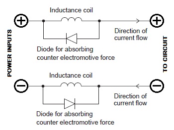
The inductors should be good enough. You might consider adding the antiparallel diodes (see picture).
I would strongly suggest leaving all of the current sensing circuitry alone, especially R712-714, R812-814 and R912-914. By changing their values You would change the circuit's behaviour too. In this case the protection circuit might not work as designed anymore and in case of a failure You would risk phosphor burn.
Playing around with the input resistors (R720-722, R820-822 and R920-922) is a different story. Together with the 470µF capacitors they work as an input filter which of course might be a target for optimization.
Depending on the position where You place the inductors, it might be necessary to replace R5/R6 (1 Ohm each) and R92/94 (2.2 Ohm each) with ones of the same value but higher power rating (maybe 1W or 2W). Because if You plan to add lots of Os-Cons at the OP-Amps and if their supply lines are still directly connected to the power inputs they would get all of the rush current from the OS-Cons...
Regards,
barclay66
| Description: |
|
| Filesize: |
28.81 KB |
| Viewed: |
13626 Time(s) |
|
Last edited by barclay66 on Mon Mar 18, 2013 3:37 pm; edited 1 time in total
|
|
| Back to top |
|
|
CxTurbo
Joined: 13 Oct 2008
Posts: 425
Location: Ontario, Canada
|
| Posted: Mon Mar 18, 2013 3:37 pm Post subject: |
|
|
| dvh99 wrote: | it`ll drop maybe a few decivolts (measure this to be sure) so i guess that won`t matter much.
did you notice an improvement? |
I never had an opportunity to do a critical viewing session  I will put the Os-Cons back on and give it a go again tonight. I will put the Os-Cons back on and give it a go again tonight.
Any thoughts on the placement of a resistor or should I just forget the resistor and do the inductors later on when I find/get the correct ones.
As I have said before I am having image stability problems that I want to nail down. I need to get larger clamp on ferrite chokes so I can see if the Stigmator wires are also the cause like it was with Nashou. From his video it looks like the same thing to me but I could be wrong. I also need to move my screen to eliminate the electronic corrections I have to make in the current location as it is still in the same spot as it was for my NEC and the Marquee is much lower from the ceiling.
James
_________________
Paradigm Studio 100's,Studio 20's,CC-690, Paradigm DSP-3400 V1 SUB
Pioneer Elite SC-35 AVR
Pioneer Elite BDP-05FD Bluray
3x Bryston 3B's
URC Complete Control Medius TX-1000 Remote
HTPC (LGA775 Q6600, 8GB DDR2, 7TB Storage) Mediaportal
Lumagen MINI 3D
Moome FULLHD-EXT V2
Audioquest Cable Top to Bottom
9501LC
|
|
| Back to top |
|
|
CxTurbo
Joined: 13 Oct 2008
Posts: 425
Location: Ontario, Canada
|
| Posted: Mon Mar 18, 2013 3:55 pm Post subject: |
|
|
| barclay66 wrote: | | CxTurbo wrote: | | Now on to the inrush. Would it be sufficient that I am going to be adding the inductors to the 5v and 15v rails or would it be better if I added a resistor in series with the current sense resistors? My only concern with the latter would be reducing the line voltage too much although I would assume that anything above 12v would not affect things overly much. |
James,
The inductors should be good enough. You might consider adding the antiparallel diodes (see picture).
I would strongly suggest leaving all of the current sensing circuitry alone, especially R712-714, R812-814 and R912-914. By changing their values You would change the circuit's behaviour too. In this case the protection circuit might not work as designed anymore and in case of a failure You would risk phosphor burn.
Playing around with the input resistors (R720-722, R820-822 and R920-922) is a different story. Together with the 470µF capacitors they work as an input filter which of course might be a target for optimization.
Depending on the position where You place the inductors, it might be necessary to replace R5/R6 (1 Ohm each) and R92/94 (2.2 Ohm each) with ones of the same value but higher power rating (maybe 1W or 2W). Because if You plan to add lots of Os-Cons at the OP-Amps and if their supply lines are still directly connected to the power inputs they would get all of the rush current from the OS-Cons...
Regards,
barclay66 |
Jorge,
I am only blowing the 1 Ohm current sense resistors at the R5/R6 positions. What would you suggest for inrush limiting upping the wattage on the R5/R6 resistors or would switching over to RXEF resettable fuses be a better option due to the higher trip current ratings? Do you think the shorted cap is the source of my issue? Was it a bad cap or caused by the inrush?
I was thinking of adding the inductors directly at the input connector in series with R5/R6 and R92/R94.
Sorry for the questions. DVH's signature says it best I think
James
_________________
Paradigm Studio 100's,Studio 20's,CC-690, Paradigm DSP-3400 V1 SUB
Pioneer Elite SC-35 AVR
Pioneer Elite BDP-05FD Bluray
3x Bryston 3B's
URC Complete Control Medius TX-1000 Remote
HTPC (LGA775 Q6600, 8GB DDR2, 7TB Storage) Mediaportal
Lumagen MINI 3D
Moome FULLHD-EXT V2
Audioquest Cable Top to Bottom
9501LC
|
|
| Back to top |
|
|
Nashou66
Joined: 12 Jan 2007
Posts: 16171
Location: West Seneca NY
|
| Posted: Mon Mar 18, 2013 3:56 pm Post subject: |
|
|
James, the marquee's are famous for the image oscillating back and forth. It is something Scott has mentioned before and difficult to find out what causes it.
Try this. Remove the green convergence cable from the CVA. fire up the PJ and put up the grids and look at them one color at a time. You will see the red and blue moving back and forth while the Green is steady. Something in either the CVA or its wave form signals is causing this.
Its the one thing I have not solved yet but I must admit I have not went into it much more than just scoping the outputs of the CVA.
Athanasios
_________________
Don't blame your underwear for your crooked ass~ unknown Greek philosopher
"Republicans believe every day is the Fourth of July, but the Democrats believe every day is April 15." --- President Reagan
One Smart Dog!!!
Marquee High Performance Bellows now shipping!!
Marquee Modifications and Performance Enhancement
Marquee C-element and Bellow removal
|
|
| Back to top |
|
|
CxTurbo
Joined: 13 Oct 2008
Posts: 425
Location: Ontario, Canada
|
| Posted: Mon Mar 18, 2013 3:59 pm Post subject: |
|
|
| Nashou66 wrote: | James, the marquee's are famous for the image oscillating back and forth. It is something Scott has mentioned before and difficult to find out what causes it.
Try this. Remove the green convergence cable from the CVA. fire up the PJ and put up the grids and look at them one color at a time. You will see the red and blue moving back and forth while the Green is steady. Something in either the CVA or its wave form signals is causing this.
Its the one thing I have not solved yet but I must admit I have not went into it much more than just scoping the outputs of the CVA.
Athanasios |
Damnit! That is the one thing that drives me nuts............. Might have to work on improving the stability of the CVA then.
It has gotten better as I go but the fact it is there bothers me. Nice to know that I am not alone I guess.
James
_________________
Paradigm Studio 100's,Studio 20's,CC-690, Paradigm DSP-3400 V1 SUB
Pioneer Elite SC-35 AVR
Pioneer Elite BDP-05FD Bluray
3x Bryston 3B's
URC Complete Control Medius TX-1000 Remote
HTPC (LGA775 Q6600, 8GB DDR2, 7TB Storage) Mediaportal
Lumagen MINI 3D
Moome FULLHD-EXT V2
Audioquest Cable Top to Bottom
9501LC
|
|
| Back to top |
|
|
barclay66
Joined: 27 Jun 2011
Posts: 1304
Location: Germany
TV/Projector: Marquee 9500 Ultra
|
| Posted: Mon Mar 18, 2013 4:14 pm Post subject: |
|
|
| CxTurbo wrote: | | I am only blowing the 1 Ohm current sense resistors at the R5/R6 positions. What would you suggest for inrush limiting upping the wattage on the R5/R6 resistors or would switching over to RXEF resettable fuses be a better option due to the higher trip current ratings? |
R5/R6 aren't there for current sensing. Together with all the caps at the +14v5/-14v5 line they form an input filter. As the Os-Cons are connected to the +14v5/-14v5 line, they produce a high current during power-up. Increasing their wattage looks like the best solution to me.
| CxTurbo wrote: | | Do you think the shorted cap is the source of my issue? Was it a bad cap or caused by the inrush? |
Absolutely sure! The shorted cap produced an increased current for the resistor(s) and let them burn up. But I don't know if it got damaged or if it had a short already.
| CxTurbo wrote: | I was thinking of adding the inductors directly at the input connector in series with R5/R6 and R92/R94.
|
I would place them right after the input connector before the +15V/-15V line gets divided into the STV9379 supply and the OP-Amp supply (so, before R5/R6).
Nevertheless I would recommend Nash's solution to the SAB noise!
Regards,
barclay66
|
|
| Back to top |
|
|
CxTurbo
Joined: 13 Oct 2008
Posts: 425
Location: Ontario, Canada
|
| Posted: Mon Mar 18, 2013 4:36 pm Post subject: |
|
|
| barclay66 wrote: | | R5/R6 aren't there for current sensing. Together with all the caps at the +14v5/-14v5 line they form an input filter. As the Os-Cons are connected to the +14v5/-14v5 line, they produce a high current during power-up. Increasing their wattage looks like the best solution to me. |
So, Do I have to worry about getting current sense replacements for this location or will any MF/CF resistor do? Just want to be sure I get the right thing. I know they are listed in the schematic as exact replacement part type. Maybe the RXEF would be a good option if they should remain a current sense type/fusible resistor?
| barclay66 wrote: | | I would place them right after the input connector before the +15V/-15V line gets divided into the STV9379 supply and the OP-Amp supply (so, before R5/R6). |
Thanks for that tip. I will try to look for a good placement in that area.
| barclay66 wrote: | | Nevertheless I would recommend Nash's solution to the SAB noise! |
For sure. I have some clamp-on chokes here but they are too small to form a loop with the cable and still close. I was able to add them to the VDM cables and also want to add them to the CVM cables too.
Thanks for your help Jorge! I appreciate it!
James
_________________
Paradigm Studio 100's,Studio 20's,CC-690, Paradigm DSP-3400 V1 SUB
Pioneer Elite SC-35 AVR
Pioneer Elite BDP-05FD Bluray
3x Bryston 3B's
URC Complete Control Medius TX-1000 Remote
HTPC (LGA775 Q6600, 8GB DDR2, 7TB Storage) Mediaportal
Lumagen MINI 3D
Moome FULLHD-EXT V2
Audioquest Cable Top to Bottom
9501LC
|
|
| Back to top |
|
|
CxTurbo
Joined: 13 Oct 2008
Posts: 425
Location: Ontario, Canada
|
| Posted: Mon Mar 18, 2013 6:08 pm Post subject: |
|
|
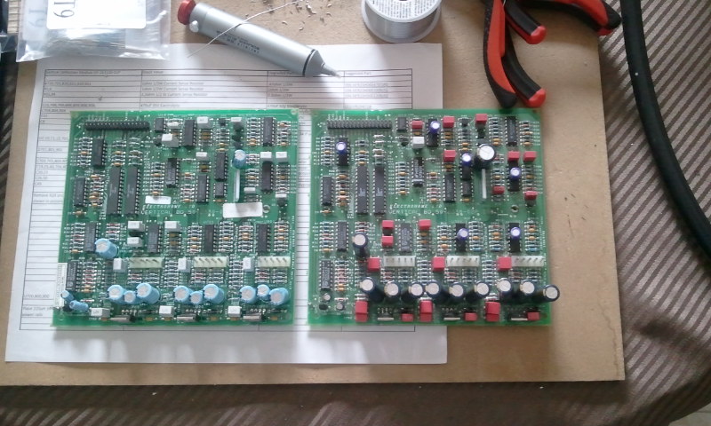
Well I am mostly finished with my heavily modded VDM.
Still need to do the inductors, Up the wattage on the 15v rail resistors and install the shunt regulator on the TDA chip.
Here is a picture to compare a bone stock VDM to my modded one.
| Description: |
|
| Filesize: |
124.95 KB |
| Viewed: |
13590 Time(s) |
|
_________________
Paradigm Studio 100's,Studio 20's,CC-690, Paradigm DSP-3400 V1 SUB
Pioneer Elite SC-35 AVR
Pioneer Elite BDP-05FD Bluray
3x Bryston 3B's
URC Complete Control Medius TX-1000 Remote
HTPC (LGA775 Q6600, 8GB DDR2, 7TB Storage) Mediaportal
Lumagen MINI 3D
Moome FULLHD-EXT V2
Audioquest Cable Top to Bottom
9501LC
|
|
| Back to top |
|
|
Nashou66
Joined: 12 Jan 2007
Posts: 16171
Location: West Seneca NY
|
|
| Back to top |
|
|
CxTurbo
Joined: 13 Oct 2008
Posts: 425
Location: Ontario, Canada
|
| Posted: Mon Mar 18, 2013 6:12 pm Post subject: |
|
|
I had to mod them. I cut them down to two "fingers" each and they fit great. I made sure to bend them in as much as possible and are tight as heck..... However it is tight.
James
_________________
Paradigm Studio 100's,Studio 20's,CC-690, Paradigm DSP-3400 V1 SUB
Pioneer Elite SC-35 AVR
Pioneer Elite BDP-05FD Bluray
3x Bryston 3B's
URC Complete Control Medius TX-1000 Remote
HTPC (LGA775 Q6600, 8GB DDR2, 7TB Storage) Mediaportal
Lumagen MINI 3D
Moome FULLHD-EXT V2
Audioquest Cable Top to Bottom
9501LC
|
|
| Back to top |
|
|
barclay66
Joined: 27 Jun 2011
Posts: 1304
Location: Germany
TV/Projector: Marquee 9500 Ultra
|
| Posted: Mon Mar 18, 2013 9:02 pm Post subject: |
|
|
| CxTurbo wrote: | | So, Do I have to worry about getting current sense replacements for this location or will any MF/CF resistor do? Just want to be sure I get the right thing. I know they are listed in the schematic as exact replacement part type. Maybe the RXEF would be a good option if they should remain a current sense type/fusible resistor? |
James,
/NERD MODE ON
Again, those resistors have nothing to do with current sensing. They only serve two purposes:
- Filtering (in conjunction with following capacitors)
- Protection (as they will safely burn away if there's a short -> Protection for the LVPS)
Current sensing with resistors can be found inside motor drivers, amplifiers and other applications driving larger currents. There You have a resistor in series with the load (e.g. the motor). The more current the load draws the more voltage can be measured across the resistor (result of the voltage drop across a resistor). These voltages are then used for limiting/protecting/controlling purposes or just to get a value for a current meter display.
/NERD MODE OFF
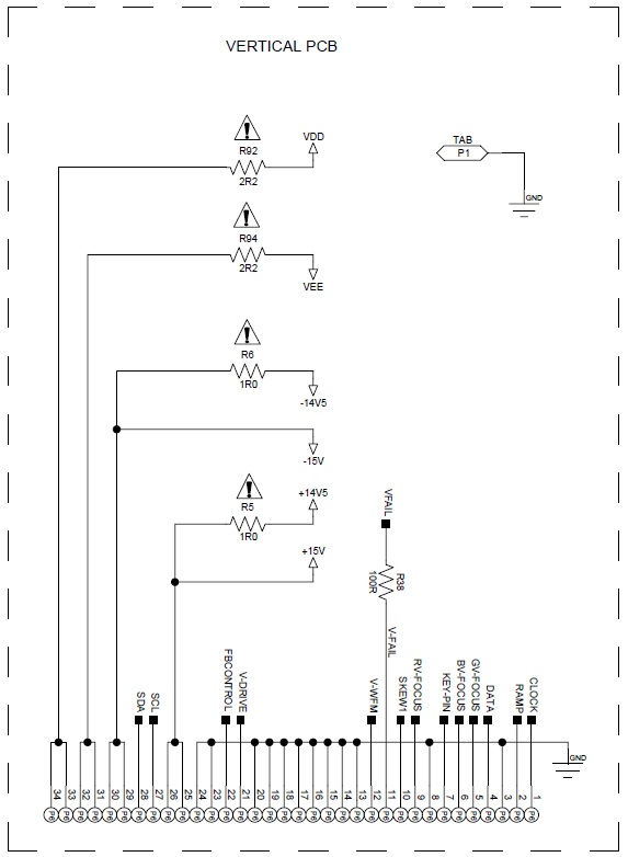
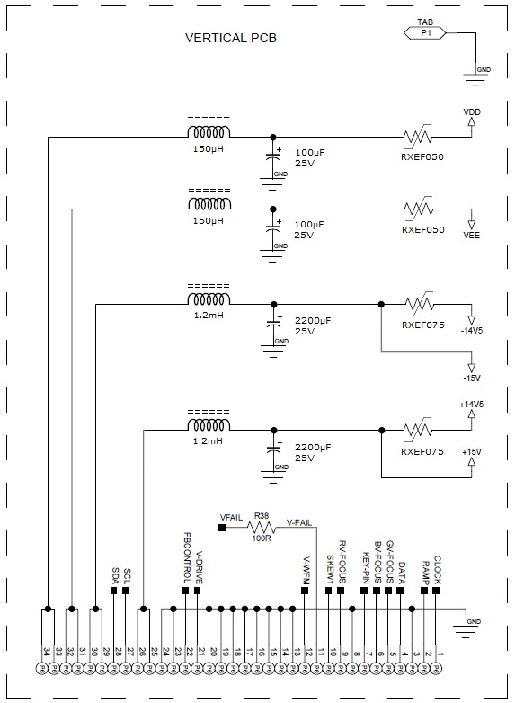
I have drawn a schematic of my VDM modifications at the power inputs (please see the original drawing and the modified one). What You can see, is that I added combinations of inductors and low-ESR electrolytic capacitors (Panasonic FM series) and I replaced the fusible resistors with polyswitch RXEFs.
Apart from that I did replace:
- R720/820/920 with RXEF075 and each combination of R721/722, R821/822 and R921/922 with RXEF135.
- All electrolytics with Panasonic FM series with a slightly higher voltage rating
- All STV9379 with STV9379A
- All TL084 with TLE2074
- Voltage Divider at U4 with LM4040
- U17 (LM431) with LM4040
I didn't add any Os-Cons because the result met my expectations. If I would consider doing so, I would use quite small values (something between 1µF and 4.7µF) in order to avoid any rush current problems.
Regards,
barclay66
| Description: |
|
| Filesize: |
67.89 KB |
| Viewed: |
13561 Time(s) |
|
| Description: |
|
| Filesize: |
83.78 KB |
| Viewed: |
13562 Time(s) |
|
Last edited by barclay66 on Mon Mar 18, 2013 10:27 pm; edited 1 time in total
|
|
| Back to top |
|
|
Nashou66
Joined: 12 Jan 2007
Posts: 16171
Location: West Seneca NY
|
|
| Back to top |
|
|
|
|