| Author |
Message |
dvh99
Joined: 25 Dec 2009
Posts: 2158
Location: nederland
|
| Posted: Thu Feb 03, 2011 10:15 pm Post subject: |
|
|
ah i see.
and yes i know those wet tants are expensive lol.
nash have you tried them?
_________________
1 answer always poses multiple questions.
marquee 9500ultra HD10L moome hdmi1.3 v3+ some mods.
|
|
| Back to top |
|
 |
Revox
Joined: 13 Feb 2008
Posts: 158
|
| Posted: Fri Feb 04, 2011 11:31 am Post subject: |
|
|
As i can understand now, there are many possiblities for a pixel peak circuit.
playing around on the VIM will be much easier than on the Necboard. Sorry if i ask again, but on which opamp was the peaking simmulated?
Do you think it changes the performance on 1920x1080 75hz I ?
|
|
| Back to top |
|
|
dvh99
Joined: 25 Dec 2009
Posts: 2158
Location: nederland
|
| Posted: Fri Feb 04, 2011 6:38 pm Post subject: |
|
|
i guess the simulation was done with clc449.
you mean if the peaking circuit improves resolving the resolution at 1920*1080 75hz then the answer is yes, if there is much to be gained with an additional peaking on the neckboard i have to see this yet.
the peaking on the vim is with one pj almost mandatory if you want best results, the neckboard is extra.
when you are ready adjusting the peaking on the vim do not change timing settings or contrast as this will effect the rise fall again.
i have the part numbers of the varicaps here and the trimming tool you need.
varicap
http://uk.farnell.com/murata/tz03r300f169b00/capacitor-variable-5-2-to-30pf/dp/1685439?Ntt=16854391
trimming tool with ceramic head.
http://uk.farnell.com/murata/kmdr010/trimming-tool-tzc03/dp/3531764?Ntt=3531764
edit: the el5166 is a drop in replacement and outperforms the clc449.
i think mike is currently playing with some others but the el5166 is fine with me.
with some fiddling i am sure i can get the ths3201 to work.
|
|
| Back to top |
|
|
Revox
Joined: 13 Feb 2008
Posts: 158
|
| Posted: Fri Feb 04, 2011 7:06 pm Post subject: |
|
|
Is the tool recommended?
The Caps are aviable in a store next to me, not the tool.
It will be not possible to trim the vim inside the pj. So i need to pull the vim out on every cap change.
Contrast and all Timmings were "glued" for long time. Sometimes i change the contrast a little bit (5%).
Tomorow ill search in the schematics and will upload a screenshot, because ill be totaly safe not doing something wrong.
Seemes that this will be a good investigation of 2 ;-P
I use 1920x1080 interlaced so the videobandwith is realy not very high.
|
|
| Back to top |
|
|
dvh99
Joined: 25 Dec 2009
Posts: 2158
Location: nederland
|
| Posted: Fri Feb 04, 2011 7:18 pm Post subject: |
|
|
the tool hasnt got any metal parts so its absolutely safe to use and it works perfect and because of the ceramic head the (capacitive setting) does not change when you take the tool of the varicap after adjusting.
i would get this tool for safety and ease of use.
_________________
1 answer always poses multiple questions.
marquee 9500ultra HD10L moome hdmi1.3 v3+ some mods.
|
|
| Back to top |
|
|
dvh99
Joined: 25 Dec 2009
Posts: 2158
Location: nederland
|
| Posted: Fri Feb 04, 2011 7:25 pm Post subject: |
|
|
oh you will need an extension board or adjust the caps inside the pj while the pj is running.
you cannot (possible but a real pita) adjust the caps and hope its right.
like i said its possible but the taking out of the vim and turning the pj on and off every time cant be good, besides the pj has to be warmed up a so it will take forever to get it right.
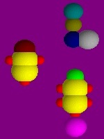
i use this pattern

|
|
| Back to top |
|
|
Revox
Joined: 13 Feb 2008
Posts: 158
|
| Posted: Sun Feb 06, 2011 3:23 pm Post subject: |
|
|
Thanks for the pattern. But there is no possibility to expand the VIM Board, so i try to get the right setting pulling the board mabe 10times out. I think the connection must cope with it. Or do you have any ideas adjusting it in the pj without the extansion board?
Arent the setting the same for all colours?
I did a few Simulations but i dont understand something:
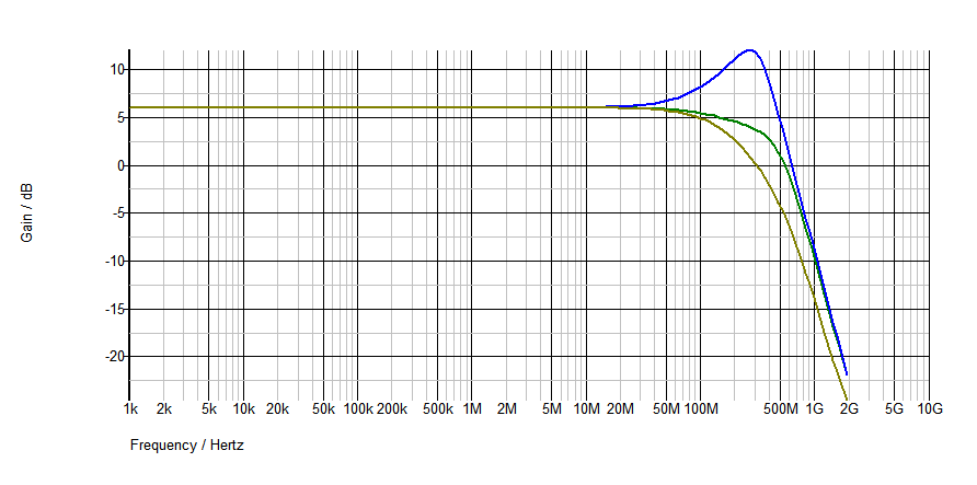
You optimise the time of rising with the peaking circuit. For the time the cap needs to be charged the gain os only limited by the 10Ohm resistor around 24.
But why is there only one good band of frequency? I think the rising time of a black and white pattern is everytime the same?
Thats the same thing i noticed by my simmulation, it does not matter how often one Impuls is feed into the circuit.
So what should i do to see the negative side of the mod in my simmulation.
The only Problem is that you do manipulate the Bode blot to a high frequency gain (adding some high frequency noise).
Simulation was done with symmetrix and the model of the CLC 449.
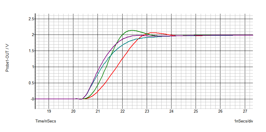
The Red curve was simmulated with a different rise time (what rise time is practical?)
One last question: The passive lowpassfilter with the 75Ohm and the 12p cap in the simulation before it was this the equivalent circuit of the Neckboard?
P.s.: Yesterday i adjusted a Barco 909 i did not find do manipulate astig settings. And i dont understand what "digital sharpness" does to the testpattern? It was interesting what a differnce was between the low mid and high frequency peaking. I never saw it before in a Pj interface.
| Description: |
|
| Filesize: |
10.55 KB |
| Viewed: |
10427 Time(s) |
|
| Description: |
|
| Filesize: |
9.54 KB |
| Viewed: |
10427 Time(s) |
|
|
|
| Back to top |
|
|
Nashou66

Joined: 12 Jan 2007
Posts: 16171
Location: West Seneca NY
|
| Posted: Sun Feb 06, 2011 3:48 pm Post subject: |
|
|
For your last question, the peaking circuit on the vim is done to compensate for the early roll of on the VNB I would think if I understood what TSE was trying to do. So by exaggerating the curve early when it gets to the op amp on the VNB that acts as a Low pass filter. This then results in a better signal, the peak would get smoothed out to a better looking response curve, not perfectly square, but still better than without the peaking circuit. I think the circuit for the op amp (RGB) on the VNB is fairly close to the VIM's RGB op Amp circuit. I don't think There is a DC restore circuit on the VNB as is on the VIM (TLO71).
Remember this is only on the 2035-02P vims not the dual RGB op amp design of the 2035-03P vim.
Not sure why there is only one good band of frequency, someone more knowledgeable than I will have to answer that. maybe its how the data is figured out in the Symetrix program? TSE uses Spice models.
Revox can you change the CLC449 to the intersill EL5166 and see what those results look like in that program? I want to try that op amp on my VIM which has the peaking circuit.
But I must say it does work very well . Revox I suggest you angle the vari caps so you can adjust them with the cover above the VIM off.
Athanasios
Athanasios
_________________
Don't blame your underwear for your crooked ass~ unknown Greek philosopher
"Republicans believe every day is the Fourth of July, but the Democrats believe every day is April 15." --- President Reagan
One Smart Dog!!!
Marquee High Performance Bellows now shipping!!
Marquee Modifications and Performance Enhancement
Marquee C-element and Bellow removal
|
|
| Back to top |
|
|
Revox
Joined: 13 Feb 2008
Posts: 158
|
| Posted: Sun Feb 06, 2011 4:11 pm Post subject: |
|
|
Thats a good idea, take the cover off and do the Adjustment through the middle of the bnc connectors.
Now i remember that, there is no shield cover between the VIM and the second Input board (Svideo and other inputs). So ill have even more space than i thought first.
The problem with the simmulation is, that i have not the practical experience. I simulated a shematic it the build circuit was crap. So i juse a simmulation for understanding a circuit and have a first idea. For the peaking circuit it helps me a lot. The interesting thing is, that my caps are around 3-6pF and the ones i should use is 10-20pF, so you can see there is still a big difference betwen theory and praxis. Of corse you can desing the simulation more practical with better knowlage than i have.
But i know that when the simmulation is realy strange, i should not try it in praxis.
Very interesting, the little database of symmetrix has got your elxxx chip.
Computer says: Every cap over 500f do oszillate!
3pf:
| Description: |
|
| Filesize: |
10.25 KB |
| Viewed: |
10407 Time(s) |
|
|
|
| Back to top |
|
|
Nashou66
Joined: 12 Jan 2007
Posts: 16171
Location: West Seneca NY
|
|
| Back to top |
|
|
Revox
Joined: 13 Feb 2008
Posts: 158
|
| Posted: Sun Feb 06, 2011 5:28 pm Post subject: |
|
|
Shure it is the resistor (100ohm looks better) in the simulation. But do you really know if the equivalent circuit of the Neckboard is close enough to praxis?
Only thing i guess from this simulation is that this opamp is much more unstable than the clc.
500f is nearly nothing so its possible to have a capacity always connected with a low resistance between the pins of the opamp.
I hope someone like dvh can teach me a little bit in the negative things of peaking.
|
|
| Back to top |
|
|
1031
Joined: 22 Mar 2006
Posts: 657
Location: Finland
|
| Posted: Sun Feb 06, 2011 6:54 pm Post subject: |
|
|
| Revox wrote: |
One last question: The passive lowpassfilter with the 75Ohm and the 12p cap in the simulation before it was this the equivalent circuit of the Neckboard?
. |
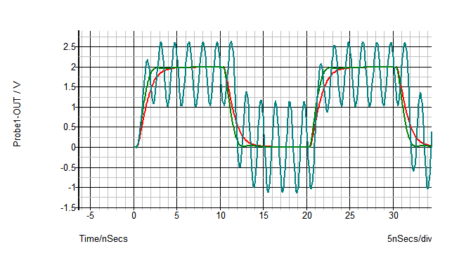
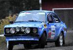
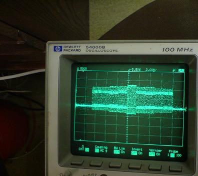
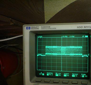
If i recall correct that 12pF/75ohm was "simulated sd5401" chip that is bottleneck on Vim´s signalway. If you look those "scope shots" that i posted , there is what happens when signal goes thru sd5401 ( scopes probe plays role there also)
That peaking circuit tryes to compensete attenuation that happens on sd5401
Here is some more scope shots from my dg612 project
Testpattern was feedet to vim (4,3,2,1,2,3,4 on/off vertical lines) and if you look "signal entry..) picture you notice that in the midde (where is 1on 1off part) signal seems stronger, that comes from probe, so signal out seems flat but it should look more like that "singnal entry.." picture.
There is no peaking at frist op-amp stage, just difference on those switch circuit chips.
| Description: |
| testpicture that i used in those tests |
|
| Filesize: |
88.45 KB |
| Viewed: |
7350 Time(s) |

|
| Description: |
|
| Filesize: |
27.28 KB |
| Viewed: |
10366 Time(s) |
|
| Description: |
|
| Filesize: |
27.53 KB |
| Viewed: |
10366 Time(s) |
|
| Description: |
|
| Filesize: |
26.82 KB |
| Viewed: |
10366 Time(s) |
|
_________________
Marquee 9500LC (Frankenyokes / Thomas electric tubes / HD-10L / +many mod´s)
DVDO VP-50
New hobby, Rally
http://www.youtube.com/watch?v=vX2Rtpr1njs
http://www.youtube.com/watch?v=6ZP9FEFXV5c
http://www.youtube.com/watch?v=j065vei6j6s
http://www.facebook.com/pages/JTS-Racing-team/204443719572685
|
|
| Back to top |
|
|
Nashou66
Joined: 12 Jan 2007
Posts: 16171
Location: West Seneca NY
|
| Posted: Sun Feb 06, 2011 7:22 pm Post subject: |
|
|
| Revox wrote: | Shure it is the resistor (100ohm looks better) in the simulation. But do you really know if the equivalent circuit of the Neckboard is close enough to praxis?
Only thing i guess from this simulation is that this opamp is much more unstable than the clc.
500f is nearly nothing so its possible to have a capacity always connected with a low resistance between the pins of the opamp.
I hope someone like dvh can teach me a little bit in the negative things of peaking. |
I have tired this op amp and from real world video it looks better to my eyes.
On my new marquee's i have not changed out that op amp because of the peaking circuit. Although the best
way to know is to try it. Might have to at some point.
Jarmo is right, the peaking circuit is after the op amp and does try to make up for the BW limit of the SD5401. I was going from memory. I have never found out what the BW for that chip is, I have the Callogic Data sheets but no specs on BW. I do know its switching speed is 1ns. I think that is the fastest I have seen for that type of chip. What is the speed of the DG chip jarmo? Is that what the extra noise might be? the slower speed?
EDIT: Just checked the speeds, the on and off time for the SD5401 is 1ns
The DG612 is 12ns on and 8ns off, for a total of 20ns compared to 2ns. that is a big difference Id think
Athanasios
_________________
Don't blame your underwear for your crooked ass~ unknown Greek philosopher
"Republicans believe every day is the Fourth of July, but the Democrats believe every day is April 15." --- President Reagan
One Smart Dog!!!
Marquee High Performance Bellows now shipping!!
Marquee Modifications and Performance Enhancement
Marquee C-element and Bellow removal
Last edited by Nashou66 on Sun Feb 06, 2011 7:36 pm; edited 1 time in total
|
|
| Back to top |
|
|
1031
Joined: 22 Mar 2006
Posts: 657
Location: Finland
|
| Posted: Sun Feb 06, 2011 7:35 pm Post subject: |
|
|
| Nashou66 wrote: |
Jarmo is right, the peaking circuit is after the op amp and does try to make up for the BW limit of the SD5401. I was going from memory. I have never found out what the BW for that chip is, I have the Callogic Data sheets but no specs on BW. I do know its switching speed is 1ns. I think that is the fastest I have seen for that type of chip. What is the speed of the DG chip jarmo? Is that what the extra noise might be? the slower speed?
Athanasios |
There is no spesific Bw data for those type chips because those are not "active" , no active stages inside of chip that are related to singnal that goes trough in/out.
So bw is more summ of chips parameters (impedance/capacitance)
So "speed" parameter is here more for how fast is switching (and if that is too slow we see it inproper side blanking..)
http://www.datasheetcatalog.org/datasheet/vishay/70057.pdf
What extra noise?
_________________
Marquee 9500LC (Frankenyokes / Thomas electric tubes / HD-10L / +many mod´s)
DVDO VP-50
New hobby, Rally
http://www.youtube.com/watch?v=vX2Rtpr1njs
http://www.youtube.com/watch?v=6ZP9FEFXV5c
http://www.youtube.com/watch?v=j065vei6j6s
http://www.facebook.com/pages/JTS-Racing-team/204443719572685
|
|
| Back to top |
|
|
Nashou66
Joined: 12 Jan 2007
Posts: 16171
Location: West Seneca NY
|
|
| Back to top |
|
|
Revox
Joined: 13 Feb 2008
Posts: 158
|
| Posted: Sun Feb 06, 2011 7:41 pm Post subject: |
|
|
Cool Idea to use the graphics card as a highspeed 8bit? signal Generator.
You are right, that its possible to guess the transfairfunktion of the SD 5401 but it is not possible to see the form of the squarewave.
The amplitude must be realy like a exp funktion at this frequency.
Sorry when i annoy you! But i realy stucked thinking why the peaking circuit works only well on one frequency 
Not knowing the chematics exactly, but am i right that the menu is only on the green colour? So there is no reason to use it on the blue and red colour. So Blanking with this chip to, seems logical for me.
|
|
| Back to top |
|
|
Nashou66
Joined: 12 Jan 2007
Posts: 16171
Location: West Seneca NY
|
| Posted: Sun Feb 06, 2011 7:59 pm Post subject: |
|
|
Not annoyed at all. Always like learning stuff. Im more of a hands on person when it comes to Modding. i try it look at it and then decide, i only recently got a scope and still have trouble trying to use it to find certain noise or waves others find very easy.
But from my comparison of a VIM with the peaking circuit and one with out for high frequency use id rather have it than not have it.
if your just running 720p@60 or simliar pixel clock rates a normal vim is fine, but when your up to the frequency i am running on each PJ for my Blend 1064x800@96hz the peaking circuit helps. Dialing it in is the hard part. I keep forgetting that contrast and brightness along with G2 and Drive also have an affect on it. And because of that Doing color calibration for a perfect blend is hard.After doing a 2 point color calibration I keep forgetting to look at the peaking circuit again to see how it may have changed.
Also with the blend the test pattern looks different in the center of the tube than on the edges, so now you have to use Zone Contrast modulation there to fix that area, then fixing that area alters the center a bit. It is very time consuming for doing a perfect edge to edge
uniform lumens and color calibration.
I drifted of topic a bit but that peaking circuit does play into blending more than I would like.
Athanasios
_________________
Don't blame your underwear for your crooked ass~ unknown Greek philosopher
"Republicans believe every day is the Fourth of July, but the Democrats believe every day is April 15." --- President Reagan
One Smart Dog!!!
Marquee High Performance Bellows now shipping!!
Marquee Modifications and Performance Enhancement
Marquee C-element and Bellow removal
|
|
| Back to top |
|
|
Revox
Joined: 13 Feb 2008
Posts: 158
|
| Posted: Sun Feb 06, 2011 9:00 pm Post subject: |
|
|
The problem for me is that i do even not understand why peaking has something to do with contrast? I thought that the contrast setting has only an influence on the height of an Signal? And that seems to be not influenced by the peaking circuit? When i say that the risetime of a signal is the same anyway, the overall rise time is different at different contrast settings. But according to my simulation, the rise time does not matter much.
I use 1980p at 37hz (75hz I), seems not so much away from your resolution. I am thinking about switching to progressiv. But 1920x1080 is hard at 75Hz P (50Hz is indiscutable).
|
|
| Back to top |
|
|
dvh99
Joined: 25 Dec 2009
Posts: 2158
Location: nederland
|
| Posted: Mon Feb 07, 2011 12:54 am Post subject: |
|
|
revox about the resistor value, scott recommends a 200ohm pot and the cap from the link with the leads as short as possible.
make sure the pot isnt set to 0 ohms when you start off though.
after you have found the best value for the pot replace the pot with a fixed resistor.
the 10ohm value worked fine for me so i left it at that.
this peaking circuit works very well on my modified vim which is in fact a 03vim with el5166 on the vim and neckboards.
if you want to adjust the caps inside the pj i would certainly get the tool so you are sure you cannot short anything inside.
its a 6 or 7 dollars tool but can save you a big headache.
|
|
| Back to top |
|
|
tse
Joined: 03 May 2006
Posts: 1014
Location: Sweatbucket, Fl.
|
| Posted: Mon Feb 07, 2011 1:35 am Post subject: |
|
|
| Revox wrote: | The problem for me is that i do even not understand why peaking has something to do with contrast? I thought that the contrast setting has only an influence on the height of an Signal? And that seems to be not influenced by the peaking circuit? When i say that the risetime of a signal is the same anyway, the overall rise time is different at different contrast settings. But according to my simulation, the rise time does not matter much.
I use 1980p at 37hz (75hz I), seems not so much away from your resolution. I am thinking about switching to progressiv. But 1920x1080 is hard at 75Hz P (50Hz is indiscutable). |
It is a slew rate thing. The neck card is fairly constant with slew rate. So if a 30V transition takes 1ns then a 60V transition takes 2ns. That is why the amount of high frequency overdrive is different with contrast setting. The three colors need a different drive level to get good gray scale. The red, especially, needs much less drive than the green. The peaking for red will be less than for green. There is a limit to the benefit from overdriving with peaking. There will be gains up to a point but somewhere the overdrive does no more. It is best to set desired light output and gray scale then adjust peaking for one on/ one off vertical lines equal to one on/ one off horizontal lines.
Scott
_________________
"Were we directed from Washington when to sow and when to reap, we would soon want bread."
Thomas Jefferson
|
|
| Back to top |
|
|
|
|


