| Author |
Message |
mcpherv
Joined: 15 Jan 2007
Posts: 13
|
| Posted: Mon Jan 31, 2011 4:55 am Post subject: |
|
|
Hey, I ended up using one of the Vishay DG611/612/613 series to replace the sd401. Took some jerry-rigging into place, but it worked flawlessly. Not too sure how much difference it really made to be honest, but it DOES work - just need to replace it with the appropriate variant (can't remember if a normally open or normally closed configuration is required of the switch). High voltage video pathway section of the neckboards are really the limiting area in terms of bandwidth... and its hard to do much about that. The rest of the path can be improved though, and does make a nice improvement.
Glad to see people are still pursuing this.
Last edited by mcpherv on Mon Jan 31, 2011 11:45 am; edited 1 time in total
|
|
| Back to top |
|
 |
Nashou66

Joined: 12 Jan 2007
Posts: 16171
Location: West Seneca NY
|
|
| Back to top |
|
|
1031
Joined: 22 Mar 2006
Posts: 657
Location: Finland
|
|
| Back to top |
|
|
1031
Joined: 22 Mar 2006
Posts: 657
Location: Finland
|
|
| Back to top |
|
|
dvh99
Joined: 25 Dec 2009
Posts: 2158
Location: nederland
|
| Posted: Mon Jan 31, 2011 8:13 am Post subject: |
|
|
i have some different inductor values now to play with and some varicaps so i can undo the limiting factor on the neckboards.
i will report later in another thread.
hope to get this done this week, will try the different inductors on green first.
_________________
1 answer always poses multiple questions.
marquee 9500ultra HD10L moome hdmi1.3 v3+ some mods.
|
|
| Back to top |
|
|
mcpherv
Joined: 15 Jan 2007
Posts: 13
|
| Posted: Mon Jan 31, 2011 11:58 am Post subject: |
|
|
| dvh99 wrote: | i have some different inductor values now to play with and some varicaps so i can undo the limiting factor on the neckboards.
i will report later in another thread.
hope to get this done this week, will try the different inductors on green first. |
Can't wait to see the results on that one... My impression from a few years back was that the bandwidth of the large transistors, along with the capacitance of the circuit was the major limiting factor. However, the inductors do affect the shape of the waveform, and at the time, I thought you could maybe somewhat compensate for the rounding of the waveform as it passes through the neckboards by exaggerating the edge of the waveform perform it goes into the high voltage circuit (ie. ringing...).
|
|
| Back to top |
|
|
mcpherv
Joined: 15 Jan 2007
Posts: 13
|
| Posted: Mon Jan 31, 2011 12:02 pm Post subject: |
|
|
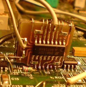
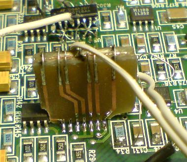
| 1031 wrote: | I have also used dg612 in place of sd5401 for some time now.. I never got it working 100% perfect, so i´m about to test Mikes "mini board" that replaces video section of that sd5401..
But someone who likes to test dg612.. Here is how i did that mod
Most problems what i had with that dg612 board was related to onscreens. |
Thats honestly a more elegant solution than I ever did - I ended up using wiring to hook up the chip upside down overtop of the sd5401. I think I only ever switched out the primary video path part of the switch and left the other parts in place if I remember right. I got something comparable in terms of sharpness outcome. Also, never had a scope to look at the waveform, but after all my mods, there wasn't a lot of obvious noise anymore that I could see by looking into the tube faces on a still screen or on the windows desktop, etc.
|
|
| Back to top |
|
|
Nashou66
Joined: 12 Jan 2007
Posts: 16171
Location: West Seneca NY
|
| Posted: Mon Jan 31, 2011 12:51 pm Post subject: |
|
|
I probably would have done that mod as you say McPherve. Its possible the board itself is picking up noise , but since you have not scoped it its hard to say if your had the noise as well.
The peaking circuit on the vim that Scott at VDC is something you should see. it brings the pre amp up to about 240 mhz pixel clock.
Athanasios
_________________
Don't blame your underwear for your crooked ass~ unknown Greek philosopher
"Republicans believe every day is the Fourth of July, but the Democrats believe every day is April 15." --- President Reagan
One Smart Dog!!!
Marquee High Performance Bellows now shipping!!
Marquee Modifications and Performance Enhancement
Marquee C-element and Bellow removal
|
|
| Back to top |
|
|
mcpherv
Joined: 15 Jan 2007
Posts: 13
|
| Posted: Mon Jan 31, 2011 11:39 pm Post subject: |
|
|
Your point is well taken, and I agree regarding the no scope issue.
Hey - got a link for the peaking circuit? I found the following thread which shows the schematic for some new gen neck boards, which has a peaking circuit in the feedback loop for the video signal opamp:
http://www.avsforum.com/avs-vb/showthread.php?t=1127826
Peaking is important, I think, for exactly what TSE mentioned in that thread - to overdrive the transistors in the latter stages of the video path at high frequencies (ie. the third order harmonic of the video signal which makes up the sqaured edge of the square waveform). The signal attenuation should reduce a lot of the ringing of the waveform in the earlier stages down, but you end up with a closer-to-square wave at the tube itself, which is obviously desireable. Obviously, the tradeoff is that this is variable at different frequencies, and could add artifact at lower frequencies. Note, this attentuation would also be happening to high frequency noise introduced into the video path at the preamp stage... Just sayin (re: tradeoff/benefit of the switch replacement - faster rise time, some noise on scope).
Also, a couple years after I stopped doing all of this, I found this new analog multiplier:
http://www.analog.com/static/imported-files/data_sheets/ADL5391.pdf
Would be a PAIN to install into the circuit due to its form factor (although an adapter board would work - seems like some around here are into custom pcbs), which is a 3mm x 3mm size, but if you could get it to work, one of the main bandwidth limitations on the preamp section of the video path would be eliminated. Also as is mentioned in that thread, OPA695s rock. And multiple parallel caps for decoupling are good too...
Last edited by mcpherv on Tue Feb 01, 2011 11:24 am; edited 1 time in total
|
|
| Back to top |
|
|
Nashou66
Joined: 12 Jan 2007
Posts: 16171
Location: West Seneca NY
|
|
| Back to top |
|
|
mcpherv
Joined: 15 Jan 2007
Posts: 13
|
| Posted: Thu Feb 03, 2011 4:13 pm Post subject: |
|
|
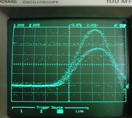
|
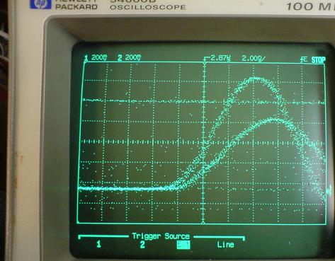
Impressive result there! Dramatic difference pre/post peaking circuit. Still could definitely be done with another amp with a higher slew rate, resulting in a shorter rise time, but that is a pretty good result!
|
|
| Back to top |
|
|
mcpherv
Joined: 15 Jan 2007
Posts: 13
|
| Posted: Thu Feb 03, 2011 4:21 pm Post subject: |
|
|
| dvh99 wrote: | i have some different inductor values now to play with and some varicaps so i can undo the limiting factor on the neckboards.
i will report later in another thread.
hope to get this done this week, will try the different inductors on green first. |
Hey, are these the inductors at positions ~L1-L7 on the neckboards in the high voltage section? If remember right, there is a paper describing the mirror cascode amplifier that talks about inductor at these positions being used to introduce peaking into the signal to compensate for signal bandwidth limitations. Playing around with these values may allow you to improve the bandwidth of the end stages of the amp circuit for some frequencies (with the same previous caveats being that it'll introduce artifact into lower frequencies).
|
|
| Back to top |
|
|
Revox
Joined: 13 Feb 2008
Posts: 158
|
| Posted: Thu Feb 03, 2011 4:30 pm Post subject: |
|
|
That is very interesting! Seems for me like for one resolution the mod can be a bigger improvement than a few other mods.
I learn for my control engineering exam in the moment, and that is realy a good transfair of this knowledge!
The problem of this big thread is, that you can only can guess what to mod if you read carfully throught the whole post.
So is it possible for you collect a few info?
To snapshot the part in the schematics of this VIM (might be possible for all VIMs or only one special?).
It would be very nice to, if you can add the mod parts via mspaint (but this is only if you have the time!).
Greetings from Berlin, Stefan
|
|
| Back to top |
|
|
dvh99
Joined: 25 Dec 2009
Posts: 2158
Location: nederland
|
| Posted: Thu Feb 03, 2011 5:05 pm Post subject: |
|
|
mcpherv, scott explained a bit about this in another thread.
https://www.curtpalme.com/forum_archived/viewtopic.php@t=24037.html
i haven`t played with it sorry  . .
the muratas have high q at 100mhz so i expect much of them.
_________________
1 answer always poses multiple questions.
marquee 9500ultra HD10L moome hdmi1.3 v3+ some mods.
|
|
| Back to top |
|
|
mcpherv
Joined: 15 Jan 2007
Posts: 13
|
| Posted: Thu Feb 03, 2011 5:50 pm Post subject: |
|
|
Here's the patent for the mirror cascode amplifier used by the neckboards as the high voltage amp stage - describes the circuit in detail.
| Description: |
|

Download |
| Filename: |
Mirror cascode amp patent.pdf |
| Filesize: |
202.37 KB |
| Downloaded: |
279 Time(s) |
|
|
| Back to top |
|
|
dvh99
Joined: 25 Dec 2009
Posts: 2158
Location: nederland
|
| Posted: Thu Feb 03, 2011 5:55 pm Post subject: |
|
|
hey thanks for that 
|
|
| Back to top |
|
|
Nashou66
Joined: 12 Jan 2007
Posts: 16171
Location: West Seneca NY
|
| Posted: Thu Feb 03, 2011 6:02 pm Post subject: |
|
|
Here is the idea for adding a peaking circuit to the VNB's along with his notes on changing the Inductor values like McPherve just mentioned.
| tse wrote: | The Mot parts are definately the best for this application (the parts on the neck card have the same characteristics as the ones attached other than increased power dissipation because of the package that allows attachment to heatsink).
Sanyo made a line of video output type transistors that could be used for higher bandwidth amps but at lower voltage than needed for the projector CRTs (ok for monitors).
There are a couple of Sanyo parts with the voltage needed but required more overdriving at the limits of bandwidth to match the Mot parts.
I believe that technique could be applied to the Mot type neck cards to get increased bandwidth over standard cards. Peaking network like C68 and R101 could be added to a better opamp. L1, L2, L3, and L7 should be lower value (to resonate at higher frequency). Probably, R84 and R85 should go away. R16 and R24 values would have to be optimized. L4, L5, and L6 might have to be slightly different value.
If attempting this I would recommend first replacing the inductors with 0 ohm jumpers and setting the peaking network for quickest rise and fall times at amplifier output. Then place the inductor values to get the shortest rise and fall times.
When I did this for the new VDC neck card I used 400MHz scope, 500MHz probes (that were close to the CRT capacitance), and pulse generator with rise/fall time less than 1ns.
Scott |
I do have some of those New style Neck boards I plan to populate some day, if I ever get time...
But the Bold text is very important, interesting idea of using jumpers to set the quickness of the rise time then later playing with inductors to find distance of the rise time. If I understand what Scott was trying to say here.

Athanasios
_________________
Don't blame your underwear for your crooked ass~ unknown Greek philosopher
"Republicans believe every day is the Fourth of July, but the Democrats believe every day is April 15." --- President Reagan
One Smart Dog!!!
Marquee High Performance Bellows now shipping!!
Marquee Modifications and Performance Enhancement
Marquee C-element and Bellow removal
|
|
| Back to top |
|
|
mcpherv
Joined: 15 Jan 2007
Posts: 13
|
| Posted: Thu Feb 03, 2011 6:55 pm Post subject: |
|
|
So another member of the original mods thread played around with this with a scope a number of years ago - the rise time adjustment can cause overshoot of the signal, which is what I meant by "ringing". At the time when I was talking with them about this, we were discussing the merits of exaggerating this overshoot to improve the shape of the waveform as it goes through the latter stages of the amp.
Oh, also - there may have been another document on the mirror cascode, but I can't seem to find it right now.
|
|
| Back to top |
|
|
dvh99
Joined: 25 Dec 2009
Posts: 2158
Location: nederland
|
| Posted: Thu Feb 03, 2011 9:59 pm Post subject: |
|
|
that member is the designer of the neckboards, the godfather of the marquee on this forum. 
scott i hope its ok with you i called you the godfather, if not please dont put concrete shoes on me and dump me in the ocean.
|
|
| Back to top |
|
|
Nashou66
Joined: 12 Jan 2007
Posts: 16171
Location: West Seneca NY
|
| Posted: Thu Feb 03, 2011 10:04 pm Post subject: |
|
|
| dvh99 wrote: | that member is the designer of the neckboards, the godfather of the marquee on this forum.
scott i hope its ok with you i called you the godfather, if not please dont put concrete shoes on me and dump me in the ocean. |
Actually the member he was talking about was Bill Blue I do believe. Bill was very outspoken in the original threads and got lots of heat for it from other marquee members. Also Chis Stevens was poking is head in and out of those old threads but he was bound to secrecy for much of what he came up with. He still has some ideas floating around form an e-mail i got form him a couple months ago. His Accurate Imaging machines were special. But those wet tantalums he used all over the place are expensive!!!!!!
Athanasios
_________________
Don't blame your underwear for your crooked ass~ unknown Greek philosopher
"Republicans believe every day is the Fourth of July, but the Democrats believe every day is April 15." --- President Reagan
One Smart Dog!!!
Marquee High Performance Bellows now shipping!!
Marquee Modifications and Performance Enhancement
Marquee C-element and Bellow removal
|
|
| Back to top |
|
|
|
|