| Author |
Message |
comm
Joined: 09 Mar 2006
Posts: 46
|
| Posted: Tue Mar 18, 2008 4:31 am Post subject: |
|
|
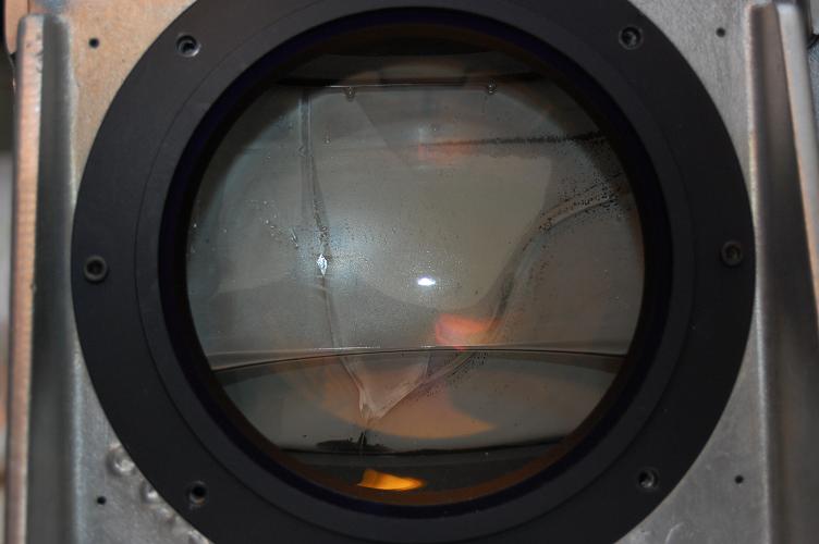
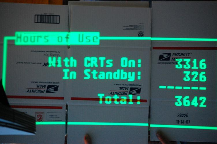
I finally in the last week have had a few days to work on the Marquee. I went through the entire chassis and realized that some glycol had leaked down in the plastic between the motherboard/backplane so I went ahead and disassembled the entire chassis. I took it down to nothing so I could take the main chassis outside to hose down. The two backplanes, the VIM, and the p/s wiring harness had some glycol residue on them that I just could not get off, so I gave the dishwasher method a shot which worked surprisingly well. Tonight I finally got it all put back together after giving the boards several days to dry and a good dose of compressed air. I left the blue neck board off and disconnected the blue HV. Plugged in the set, the power supply fans powered up and the standby light lit. I don't have a remote so I used the control software on my laptop. Tried to power it up and to my surprise it actually powered up on the first try! Red and the green both seem to work as they should and have great output. Whoever originally installed it had the brightness and contrast set much higher than I would like to see it. Probably explains why the green has a hint of wear. The projector only has 3642 total hours on it! Much less than I expected
While I was at it I measured the heater voltage at p14 on the main motherboard and it only measured something right at 4 volts. Am I measuring the the right point? I know it needs fixed, but is a low voltage as bad as a over voltage?
My next project is to find and replace the blue tube. I think I am going to give those eBay Lugs a try. Thanks again for the help.
| Description: |
|
| Filesize: |
70.23 KB |
| Viewed: |
7538 Time(s) |
|
| Description: |
|
| Filesize: |
82.46 KB |
| Viewed: |
7538 Time(s) |
|
|
|
| Back to top |
|
 |
Nashou66

Joined: 12 Jan 2007
Posts: 16171
Location: West Seneca NY
|
|
| Back to top |
|
|
1031

Joined: 22 Mar 2006
Posts: 657
Location: Finland
|
|
| Back to top |
|
|
Heywood Jablome

Joined: 12 Mar 2006
Posts: 1548
|
| Posted: Tue Mar 18, 2008 10:18 am Post subject: |
|
|
I've recently picked up a c1998 9501LC... higher hours but no dishwasher required 
I believe P14 has its' own ground reference on that chassis... fold down the rear heatsink to expose the P14 connector on the right hand side and pick up the second pin with a micro cliplead (available at rat shack)
You should be able to use the first pin (nearest you) for the ground reference, or the sheet metal of the chassis... Use the micro cliplead to get your digits out of harms way when you power up.
_________________
"Those countries which lag behind in industry, in the application of mechanics and technical chemistry, in the careful selection and utilization of natural products, where the respect for such activities does not permeate all classes of society, will unfailingly decline in prosperity. They will sink faster when neighbor states, with an energetic exchange between science and industry, go forward with renewed vitality."
-- Baron Alexander von Humboldt: 1769-1859
|
|
| Back to top |
|
|
JustGreg

Joined: 07 Mar 2006
Posts: 3098
Location: Kenosha, WI
|
| Posted: Tue Mar 18, 2008 3:23 pm Post subject: |
|
|
Nice work!!! 
Did you have to bleed the R&G? If you can't see a bubble you might want to think about doing it. Keep lots of paper towels or even better an old cotton towel handy.
And now a moment of silence for the blue tube.
Greg
|
|
| Back to top |
|
|
comm
Joined: 09 Mar 2006
Posts: 46
|
| Posted: Wed Mar 19, 2008 4:32 am Post subject: |
|
|
I went back and checked the p14 voltage with the projector on and it was right at 6.5. I hope thats not too far of spec do do much damage. Of course I am not sure if the absence of the blue tube would make a difference?
I did notice a strange spot on the red tube when running. It is not always in the same area but always on the top edge. I didn't know if this was a problem?
I have not bleed the red and green tubes yet. I checked to make sure that bellows are still spongy and they seemed fine. I guess I should have done that before I put the tubes back in, oh well.
David
| Description: |
|
| Filesize: |
49.64 KB |
| Viewed: |
7438 Time(s) |
|
| Description: |
|
| Filesize: |
69.29 KB |
| Viewed: |
7438 Time(s) |
|
|
|
| Back to top |
|
|
1031
Joined: 22 Mar 2006
Posts: 657
Location: Finland
|
|
| Back to top |
|
|
1031
Joined: 22 Mar 2006
Posts: 657
Location: Finland
|
|
| Back to top |
|
|
comm
Joined: 09 Mar 2006
Posts: 46
|
| Posted: Mon Mar 24, 2008 10:08 pm Post subject: |
|
|
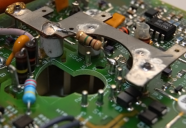
Thank you! I missed that fix entirely. Anyone know if I should stack a surface mount cap on top of resister? What size of part I should use for the cap, 805?
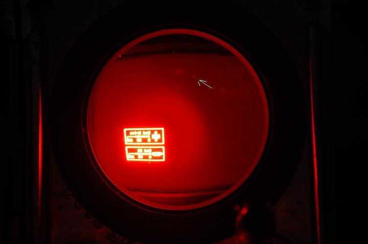
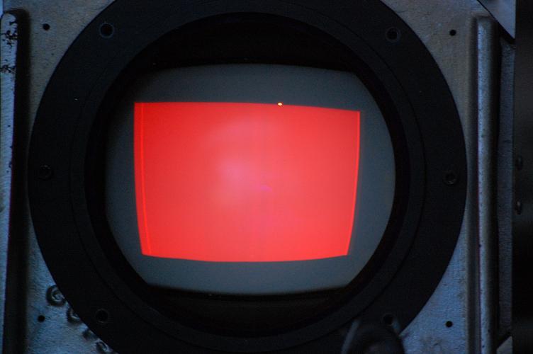
I started thinking about it more, is it normal for the raster to be lit like it is in the first picture of the red tube? That picture was taken right after the projector was powered on and the no sync error disappeared. The second picture was taken while in the G2 config for the red tube. Is it normal for the raster to light when there is no information to be displayed? Not used to the Marquee yet..
David
|
|
| Back to top |
|
|
Tim in Phoenix

Joined: 21 Oct 2006
Posts: 4409
Location: Phoenix
|
| Posted: Mon Mar 24, 2008 10:23 pm Post subject: |
|
|
| comm wrote: | I started thinking about it more, is it normal for the raster to be lit like it is in the first picture of the red tube? That picture was taken right after the projector was powered on and the no sync error disappeared. The second picture was taken while in the G2 config for the red tube. Is it normal for the raster to light when there is no information to be displayed? Not used to the Marquee yet..
David |
Have a look here: http://www.etechvideo.com/techtip1.htm Use Brite 45, Contrast 45
While you are in there, check red and green bellows for excess pressure, bellows should feel mushy when pushed inward, use a fingertip or eraser pencil. Vent if needed, remove tubes from chassis to vent or you will have glycol everywhere, it can shoot out with some force, watch your eyes.
Make sure tube castings have pivot pins installed, one pin on each side near the front.
.
|
|
| Back to top |
|
|
JustGreg
Joined: 07 Mar 2006
Posts: 3098
Location: Kenosha, WI
|
| Posted: Mon Mar 24, 2008 10:28 pm Post subject: |
|
|
I still have the dot AND the vertical line on mine. I don't notice it all unless I have my face plastered up against the lens...which is not what the designers had in mind.  I'd like to fix the vertical line tho...it's noticeable on the left of the screen. I'm just......lazy. I'd like to fix the vertical line tho...it's noticeable on the left of the screen. I'm just......lazy.
Greg
|
|
| Back to top |
|
|
1031
Joined: 22 Mar 2006
Posts: 657
Location: Finland
|
|
| Back to top |
|
|
comm
Joined: 09 Mar 2006
Posts: 46
|
| Posted: Mon Apr 14, 2008 1:09 am Post subject: |
|
|
1031, Thanks again for the help! I am going to order that along with the parts needed for the P/S fix.
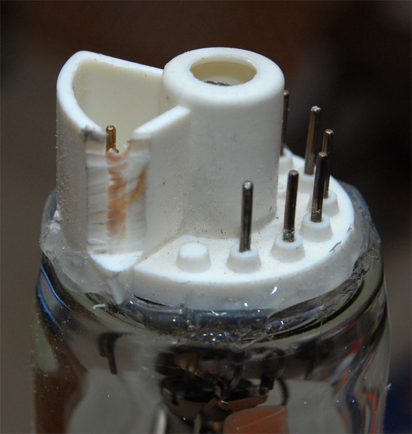
I ordered and received a LUG from the ebay seller. It looks pretty good, of course some visible wear, but it is even and covers most of the usable phosphor. The silicone is curing on it right now, hope to be filling it with glycol by next weekend.
I finished the modifications on the neckboard as well. I tied a 1M resister from pin 7 to ground, drilled out pin 6 for the g2, and removed r37 and r38. I hope this is still the preferred method. Instead of cutting to pcb to fit the tube, I shaved a little off the plastic on the end of the tube. This is how it was done on the other three tubes, so I just followed suit.
Hopefully in the next few weeks I'll be able to put it all together. Thanks again everyone for the help.
| Description: |
|
| Filesize: |
237.01 KB |
| Viewed: |
7242 Time(s) |
|
| Description: |
|
| Filesize: |
218 KB |
| Viewed: |
7242 Time(s) |
|
|
|
| Back to top |
|
|
comm
Joined: 09 Mar 2006
Posts: 46
|
|
| Back to top |
|
|
comm
Joined: 09 Mar 2006
Posts: 46
|
| Posted: Thu May 01, 2008 7:16 pm Post subject: |
|
|
I noticed that the ground strap that came off the old tube has lost quite a bit of its "stickiness" and has corroded some from the glycol. Any suggestions on what I should do to replace it or restore the stick? I though I read somewhere about a possible replacement but I cant seem to find it again.
Thanks
|
|
| Back to top |
|
|
comm
Joined: 09 Mar 2006
Posts: 46
|
| Posted: Sun May 04, 2008 11:22 pm Post subject: |
|
|
Any advice? I think I can clean most of the corrosion off, but just need to find a way to adhere it without compromising the ground.
Thanks again
|
|
| Back to top |
|
|
Nashou66
Joined: 12 Jan 2007
Posts: 16171
Location: West Seneca NY
|
|
| Back to top |
|
|
comm
Joined: 09 Mar 2006
Posts: 46
|
| Posted: Tue May 06, 2008 2:25 am Post subject: |
|
|
| Nashou66 wrote: | Not sure if this will help or work but this is a conductive tape/film made especially for electro static discharge, I think that is what the ground strap is for also, the rest of the site has other types but this is the highest temp product i could find.I would clean the end of the ground strap and maybe put some Caig contact protectant on it before applying the film over it to hold it. I have never used this but I think it should work from its description.
Cleanroom, High Temperature, ESD Tape
And this is conductive wire glue Not sure about the temp specs of this one.
Or this: Silver conductive epoxy
you might be able to use both together?
Athanasios |
Thank you Athanasios!
Thank looks exactly like the tape holding the copper strap on. Hopefully I can clean the copper up enough to salvage it.
David
|
|
| Back to top |
|
|
|
|


