| Author |
Message |
barclay66

Joined: 27 Jun 2011
Posts: 1304
Location: Germany
TV/Projector: Marquee 9500 Ultra
|
| Posted: Sun Jul 04, 2021 7:30 pm Post subject: |
|
|
| Curt Palme wrote: | | Have you put the blue CRT board onto the green tube? |
He swapped the blue and green neck boards before and it didnt change anything. So my analysis now is:
- The blue tube works perfectly as it does so being mounted at the spot of the red one
- The neck boards seem to be OK as any swaps didnt change anything
- Something is wrong with the signals/voltages going to the blue neck board
- G2 regulation is located on the neck board and is depending on signals coming from the RGB driver board (ABL and IBCL mostly)
- Next step would be replacing the RGB driver board with a known working one
|
|
| Back to top |
|
 |
Flemming
Joined: 08 Mar 2006
Posts: 26
Location: Denmark
|
| Posted: Sun Jul 04, 2021 7:42 pm Post subject: |
|
|
|
Yes, and the green works fine with the blue crt board
|
|
| Back to top |
|
|
Curt Palme
CRT Tech
Joined: 08 Mar 2006
Posts: 24396
Location: Langley, BC
TV/Projector: All of them!
|
| Posted: Mon Jul 05, 2021 12:02 am Post subject: |
|
|
|
OK, got it.
|
|
| Back to top |
|
|
Flemming
Joined: 08 Mar 2006
Posts: 26
Location: Denmark
|
| Posted: Mon Jul 05, 2021 5:57 pm Post subject: |
|
|
| barclay66 wrote: | | Curt Palme wrote: | | Have you put the blue CRT board onto the green tube? |
- Something is wrong with the signals/voltages going to the blue neck board
- G2 regulation is located on the neck board and is depending on signals coming from the RGB driver board (ABL and IBCL mostly)
- Next step would be replacing the RGB driver board with a known working one |
Any other test I can do or is it (probably) the RGB driver board that are failing?
Anyone have a RGB driver board I can buy?
Thanks
|
|
| Back to top |
|
|
barclay66
Joined: 27 Jun 2011
Posts: 1304
Location: Germany
TV/Projector: Marquee 9500 Ultra
|
| Posted: Tue Jul 06, 2021 8:58 am Post subject: |
|
|
Hi,
You could do what gjaky suggested which is measuring if the G2 voltage arrives at the blue neck board. As the G1 voltage is located at the same connector, You could measure this one as well.
BUT: G2 voltage is very high (between 500 - 1000 Volts) so You really should know what You're doing.
And You will need to do some soldering (add some extension wires) because otherwise it will be too difficult to connect the voltage meter.
If You hold the meter's tip directly at the connection point, You could slip off and cause shorts resulting in significant damage!
Again, !!!DOING MEASUREMENTS OF POTENTIALLY LETHAL VOLTAGES INSIDE A WORKING PROJECTOR IS DANGEROUS!!!
If You still want to go this route, I suggest the following:
!!!THE FOLLOWING PROCEDURE IS FOR THE EXPERIENCED OR BRAVE ONES ONLY. I WILL NOT ASSUME ANY RESPONSIBILITY FOR ANY DAMAGES TO PERSONS AND/OR EQUIPMENT!!!
- Get some insulated wire. It doesn't need to be thick. Thickness should be similar to the wires going from the chassis to the neck boards
- Wire colors should be black, red and any other color or at least any kind of marking which makes them unique. Length should be about half a meter
- Get a voltage meter. It should be able to withstand at least 1000V and should be set to DC Voltage measurement
- Mount everything back to its normal position (every tube at its location, everything connected)
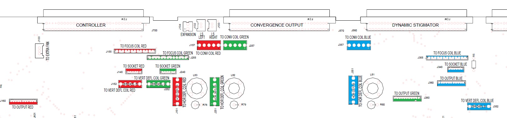
- Check the diagram attached for correct location of every cable connector
- Switch on the projector and verify that again the blue tube flashes until the projector shuts off
- Disconnect the projector from power and wait a few minutes
- Disconnect the HV wire of the blue tube
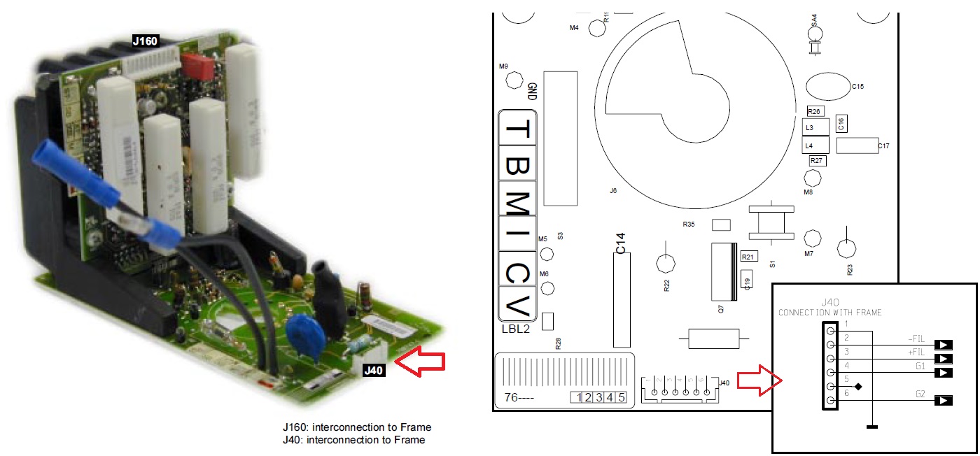
- Remove the blue neck board
- Locate the smaller connector (J40) on the neck board
- Check the second diagram attached
- Solder the black wire to pin 1 of J40 (solder side of the PCB)
- Solder the red wire to pin 6 of J40 (solder side of the PCB)
- Solder the third wire to pin 4 of J40 (solder side of the PCB)
- Mount the blue neck board back onto the blue tube and connect it to the chassis
- Find something which will allow the other ends of the wires to be fixated and separated (at least 1cm distance)
- Switch on the projector. It should stay on as the blue tube's HV is not connected
- Measure and write down the voltage between the black wire and the red wire (G2 Voltage)
- Measure and write down the voltage between the black wire and the third wire (G1 Voltage)
- Switch off the projector
- Remove the wires from the blue neck board. Make sure that the soldered pins of J40 are clean and without shorts
- Mount the blue neck board back into the projector
- If possible, do the same procedure on the green or red neck board
- Report back with the values
| Description: |
|
| Filesize: |
131.94 KB |
| Viewed: |
2916 Time(s) |
|
| Description: |
|
| Filesize: |
158.1 KB |
| Viewed: |
2916 Time(s) |
|
|
|
| Back to top |
|
|
Flemming
Joined: 08 Mar 2006
Posts: 26
Location: Denmark
|
| Posted: Tue Jul 06, 2021 10:29 am Post subject: |
|
|
Hi Barclay
I think the test you describe is a little over the top for me 
As an alternative could I try use the green neck board on the blue tube but this time keep the green neck board connected to its "green sockets". This way we know that the neck board gets the right voltage ... and the rest of the connectors on the blue tube will stay on the "blue sockets". Will this work?
|
|
| Back to top |
|
|
barclay66
Joined: 27 Jun 2011
Posts: 1304
Location: Germany
TV/Projector: Marquee 9500 Ultra
|
| Posted: Tue Jul 06, 2021 11:45 pm Post subject: |
|
|
Hi,
This wouldnt add anything to what we know already. Remember: You swapped the green with the blue neck board before. So it is obvious that a known working green neck board used at the spot of the blue tube produces the same error. So its quite clear that something is wrong with the signals/voltages being provided at the blue neck board connectors.
What You still can do: Inspect both connectors and cables for the blue neck board. Look if there are any bent pins on the neck board side and the chassis side. Check if any of the contacts has slipped out of the white connector housings.
|
|
| Back to top |
|
|
|
|