| Author |
Message |
Apfelmousse
Joined: 26 Apr 2014
Posts: 74
Location: Germany
|
| Posted: Mon Feb 26, 2018 8:07 pm Post subject: Sony G90 corner convergence issue |
|
|
Hi,
I made some experiments prior to hooking it up to the ceiling. In particular I was testing size and centering controls to find out the minimum distance between lenses and screen. With the standard lenses this seems to be around 2,20 meters, focus on the lenses near to the full CW position.
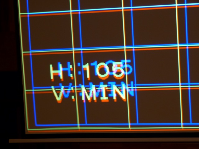
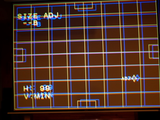
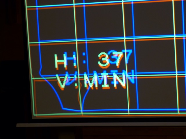
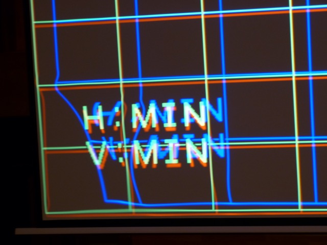
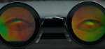
At some point I noticed a strange distortion in the lower left corner. It seems to originate from the blue horizontal circuits, as it depends on blue horizontal size setting. It appears when this setting it is below 100. I added some pics to illustrate. It influences red and to a much lesser extent, green. When blue size setting is above 100 the corner looks perfectly normal.
Anyone else noticed this?
regards
Martin
BTW: I ordered the Dallas chip - directly from Maxim. Delivery will probably take some weeks.
| Description: |
|
| Filesize: |
64.08 KB |
| Viewed: |
10298 Time(s) |
|
| Description: |
|
| Filesize: |
88.56 KB |
| Viewed: |
10298 Time(s) |
|
| Description: |
|
| Filesize: |
59.03 KB |
| Viewed: |
10298 Time(s) |
|
| Description: |
|
| Filesize: |
62.31 KB |
| Viewed: |
10298 Time(s) |
|
|
|
| Back to top |
|
 |
Curt Palme
CRT Tech
Joined: 08 Mar 2006
Posts: 24396
Location: Langley, BC
TV/Projector: All of them!
|
| Posted: Mon Feb 26, 2018 8:25 pm Post subject: |
|
|
That is usually due to too much convergence or other parameter applied. My first bit of advice though:
Check the Dallas chip date, and if it is pre-2005, DO NOT use the machine. It's a 4 digit date code on the chip, 9912, would mean 1999, 12th week of manufacture.
0542 would mean 2005, the 42 week of manufacture. You do not want to kill all 3 tubes with a spot burn due to an old Dallas chip, trust me!
if it is a later chip, then I'd reset all of the convergence zones of the blue to 128, the default, do a really careful setup using all the other controls, and then use the zone convergence minimally.
|
|
| Back to top |
|
|
Apfelmousse
Joined: 26 Apr 2014
Posts: 74
Location: Germany
|
| Posted: Mon Feb 26, 2018 8:40 pm Post subject: |
|
|
Curt,
thanks for the advice. Indeed, I made a first quick setup with the blue lens a little bit misaligned, and had some trouble doing convergence on the left side of the screen.
Promised, I'll do that properly once its up on the ceiling. My main purpose of these tests was to find out the minimum distance to my screen with the maximum raster on the tubes. The lens-program gives a minimum of 2,70 metres, but I can get much closer.
Promised, too, I'll not use the set anymore before the Dallas chip arrives. Mine is dated 98...
cheers
Martin
|
|
| Back to top |
|
|
Curt Palme
CRT Tech
Joined: 08 Mar 2006
Posts: 24396
Location: Langley, BC
TV/Projector: All of them!
|
| Posted: Mon Feb 26, 2018 8:49 pm Post subject: |
|
|
Yup, that's playing with fire! 
|
|
| Back to top |
|
|
Apfelmousse
Joined: 26 Apr 2014
Posts: 74
Location: Germany
|
| Posted: Tue Feb 27, 2018 4:17 am Post subject: |
|
|
BTW, I left the set in standby the last days. That did NOT increase the hours counter. Since I have 1300 hours on the total and 70+ on the tubes I wonder how that came.
Can it be the Dallas lost some of its memory once and now re-functions?
As I said in another thread, the tubes look new and the set is very clean inside. It even has a "new" smell when running.
cheers
Martin
|
|
| Back to top |
|
|
Apfelmousse
Joined: 26 Apr 2014
Posts: 74
Location: Germany
|
| Posted: Thu Mar 01, 2018 1:32 am Post subject: |
|
|
| Apfelmousse wrote: | Curt,
...
Promised, too, I'll not use the set anymore before the Dallas chip arrives. Mine is dated 98... |
I just received 2 Dallas chips directly from Maxim (as samples!!). Its the 70ns type with a datecode 16xy on them, so they're from 2016. Should be good, since the batteries are not drained until the chip is first used.
If I understood correctly I can just plug them in as it is and the projector will run, with serial #00000 and 0 hours on everything?
regards
Martin
|
|
| Back to top |
|
|
Curt Palme
CRT Tech
Joined: 08 Mar 2006
Posts: 24396
Location: Langley, BC
TV/Projector: All of them!
|
| Posted: Thu Mar 01, 2018 2:35 am Post subject: |
|
|
|
No, you need to initlaize them, otherwise the '31' error code will come up when you try to power up. Let's see if someone else can post how to initialize it (I am running out for dinner), otherwise I'll advise tomorrow.
|
|
| Back to top |
|
|
barclay66

Joined: 27 Jun 2011
Posts: 1304
Location: Germany
TV/Projector: Marquee 9500 Ultra
|
| Posted: Thu Mar 01, 2018 7:30 am Post subject: |
|
|
Hi,
You could send them to me together with the old chip as I have the equipment for reading/programming them. Send a PM if Youre interested.
Regards,
barclay66
|
|
| Back to top |
|
|
jbltecnicspro
Joined: 23 Apr 2016
Posts: 512
|
| Posted: Mon Mar 05, 2018 2:19 am Post subject: |
|
|
|
Not to rehash this - but why oh why did Sony use the Dallas chip instead of an EEPROM? Is there some technical advantage they offer?
|
|
| Back to top |
|
|
Curt Palme
CRT Tech
Joined: 08 Mar 2006
Posts: 24396
Location: Langley, BC
TV/Projector: All of them!
|
| Posted: Mon Mar 05, 2018 4:17 am Post subject: |
|
|
|
Electrohome did it too in the ECPs
|
|
| Back to top |
|
|
AnalogRocks
Forum Moderator
Joined: 08 Mar 2006
Posts: 26706
Location: Toronto, Ontario, Canada
TV/Projector: Sony 1252Q, AMPRO 4000G
|
| Posted: Mon Mar 05, 2018 5:03 am Post subject: |
|
|
| Curt Palme wrote: | | Electrohome did it too in the ECPs |
Should I replace my Dallas chip in my old ECP?
_________________
Tech support for nothing
CRT.
HD done right!
|
|
| Back to top |
|
|
Curt Palme
CRT Tech
Joined: 08 Mar 2006
Posts: 24396
Location: Langley, BC
TV/Projector: All of them!
|
| Posted: Mon Mar 05, 2018 5:53 pm Post subject: |
|
|
|
If you can find one, sure!
|
|
| Back to top |
|
|
jbltecnicspro
Joined: 23 Apr 2016
Posts: 512
|
| Posted: Tue Mar 06, 2018 12:02 am Post subject: |
|
|
| Curt Palme wrote: | | Electrohome did it too in the ECPs |
And I get that, being an older model that they did that. But by the time the G90's were made, surely Sony knew of their long term reliability issues? Anyone who's ever owned an IBM PS/2 computer (those all use Dallas chips) would tell you immediately that they ultimately don't last and are a pain in the ass to change, with some people going to different lengths to mod the chips to accept CR-2302 batteries.
|
|
| Back to top |
|
|
Curt Palme
CRT Tech
Joined: 08 Mar 2006
Posts: 24396
Location: Langley, BC
TV/Projector: All of them!
|
| Posted: Tue Mar 06, 2018 2:31 am Post subject: |
|
|
Sure, but:
1) I don't think Sony expected people to still have them 20+ years after they were made.
2) Sony couldn't predict (or maybe they didn't test) the fact that a dead Dallas chip could nuke tubes.
3) I'm sure in CRT projector training sessions that they may have covered the Dallas chip changing. Problem is, 10 years and 2-3 owners and techs later, do you think any of that info got passed on? Nope! AV people in general aren't interested in fixing stuff, hell, I've bought many 9" projectors from end users whose AV company told them that they were not HD compatible. By the time they found out they were, they'd already spent $10-20K on a 'HD compatible' digital. Go figure.
|
|
| Back to top |
|
|
CIR Engineering

Joined: 25 Aug 2008
Posts: 4269
Location: Chicago USA & Berlin Germany
|
| Posted: Tue Mar 06, 2018 3:40 pm Post subject: |
|
|
| jbltecnicspro wrote: | | Not to rehash this - but why oh why did Sony use the Dallas chip instead of an EEPROM? Is there some technical advantage they offer? |
Because the timer for the tubes and chassis is continuously updated and keeps the times to the second. Literally, every second three timer parameters (and quite a few other potential parameters) are updated. An EPROM would quickly fail due to exceeding its rewrite tolerance.
craigr
_________________
JETI 1501-HiRes 2nm Spectroradiometer
JETI 1211 Spectroradiometer
Photo Research PR-650 Spectroradiometer
Klein K10-A Colorimeter
Murideo Fresco SIX-G HDMI 2.x Multimedia Generator
Murideo Fresco SIX-A HDMI 2.x Analyzer
Light Illusion ColourSpace XPT Color Calibration Software
Light Illusion LightSpace XPT Pro Version 10.x Color Calibration Software
OMARDRIS JVC Software Patch to use K10-A and Jeti with JVC OEM AutoCal Software!
Sencore CR7000 CRT Tube Analyzer / Rejuvenater
Authorized Dealer for Lumagen & just about everything worth buying 
www.CIR-Engineering.com - craigr@cir-engineering.com
Phone: 865-405-6892
|
|
| Back to top |
|
|
Apfelmousse
Joined: 26 Apr 2014
Posts: 74
Location: Germany
|
| Posted: Tue Mar 06, 2018 3:44 pm Post subject: |
|
|
Hi Guys,
coming back to my initial topic: convergence issue.
I did some study of the "theory of operation" manual here on Curt's site. There'a a DA board generating basic waveforms that are fed into the DB board that adds the zone control. Bottem left seems to be zone #7. But this is for keystone and pincushion only...
What I do not understand: where is the convergence done? And I can do these settings for each colour - but there's only one DA board. I would have expected some circuitry for each colour.
Can anybody enlighten me?
cheers
Martin
BTW: I got a rather modern programmer (a BeeProg+) from my lab today. It supports tens of thousands of chips, in particular all Dallas types. The one's I received from Maxim are 70ns type, which should work in place of a 120ns chip if the circuitry has been properly designed... we'll see
|
|
| Back to top |
|
|
CIR Engineering
Joined: 25 Aug 2008
Posts: 4269
Location: Chicago USA & Berlin Germany
|
| Posted: Tue Mar 06, 2018 3:52 pm Post subject: |
|
|
Also, why is your vertical amplitude set to MIN? I don't think it would cause your issues because I modify the vertical deflection board for running the G90 with 3D so that it can squish the vertical much more, but I think Curt is right and you are pushing a bunch of different values at the same time. If you go too far the projector will shut down and you will be unable to access the video memory again without the projector shutting down. Then you will either have to apply no signal and reset to factory defaults or go into "expert mode" memory managment and delete the memory for the resolution you are working with and start from scratch.
As far as horizontal goes, you can set the magnetics on the horizontal deflection board once you have the projector in its proper mounting location. If you take the decorative cover off the G90 you'll notice three holes in the cover of the horizontal deflection board. You do not even need to open the case!
Set the horizontal amplitude to neutral 128 on all there tubes in the service menu.
Align the three tubes mechanically, such that their outer edges are equidistant from the screen edges on the horizontal while the image is centered in the tube face horizontally.
Put up a cross hatch pattern from an external source.
Use an Allen wrench that fits the magnets behind the three holes and adjust this such that all thee tubes have the correct width at 128 +/-5 for the horizontal amplitude.
You may need to iterate a little bit because of the magnetic change due to the Allen wrench.
This will mitigate any need to push the horizontal amplitude much in either direction.
craigr
_________________
JETI 1501-HiRes 2nm Spectroradiometer
JETI 1211 Spectroradiometer
Photo Research PR-650 Spectroradiometer
Klein K10-A Colorimeter
Murideo Fresco SIX-G HDMI 2.x Multimedia Generator
Murideo Fresco SIX-A HDMI 2.x Analyzer
Light Illusion ColourSpace XPT Color Calibration Software
Light Illusion LightSpace XPT Pro Version 10.x Color Calibration Software
OMARDRIS JVC Software Patch to use K10-A and Jeti with JVC OEM AutoCal Software!
Sencore CR7000 CRT Tube Analyzer / Rejuvenater
Authorized Dealer for Lumagen & just about everything worth buying
www.CIR-Engineering.com - craigr@cir-engineering.com
Phone: 865-405-6892
|
|
| Back to top |
|
|
CIR Engineering
Joined: 25 Aug 2008
Posts: 4269
Location: Chicago USA & Berlin Germany
|
| Posted: Tue Mar 06, 2018 4:00 pm Post subject: |
|
|
| Apfelmousse wrote: | Hi Guys,
coming back to my initial topic: convergence issue.
I did some study of the "theory of operation" manual here on Curt's site. There'a a DA board generating basic waveforms that are fed into the DB board that adds the zone control. Bottem left seems to be zone #7. But this is for keystone and pincushion only...
What I do not understand: where is the convergence done? And I can do these settings for each colour - but there's only one DA board. I would have expected some circuitry for each colour.
Can anybody enlighten me?
cheers
Martin
BTW: I got a rather modern programmer (a BeeProg+) from my lab today. It supports tens of thousands of chips, in particular all Dallas types. The one's I received from Maxim are 70ns type, which should work in place of a 120ns chip if the circuitry has been properly designed... we'll see |
The worst thing about the G90 is that it is very complex. Geometry is a product of several boards in between the tubes, but is also related to the PA board and the small boards right near the built in remote. If there is a problem, trouble shooting will be a matter of board swapping many boards. The DA board only generates waveforms which I recall are common for all three tubes. Each tube then has s separate channel for geometry and convergence.
70ms Dallas chips are fine; they are no better of worse than any other speed chip in the G90. I always buy whichever speed is cheapest at the time.
Make sure you don't whip out your Dallas chip when you try to read the original. It is easy to mess up that chip. Make sure to write something to one of your new chips first and then verify it. That way you can be reasonably sure that you won's accidentally wipe the original. I've had several cases of Dallas chips being corrupt due to minor errors so it can be a real problem.
craigr
_________________
JETI 1501-HiRes 2nm Spectroradiometer
JETI 1211 Spectroradiometer
Photo Research PR-650 Spectroradiometer
Klein K10-A Colorimeter
Murideo Fresco SIX-G HDMI 2.x Multimedia Generator
Murideo Fresco SIX-A HDMI 2.x Analyzer
Light Illusion ColourSpace XPT Color Calibration Software
Light Illusion LightSpace XPT Pro Version 10.x Color Calibration Software
OMARDRIS JVC Software Patch to use K10-A and Jeti with JVC OEM AutoCal Software!
Sencore CR7000 CRT Tube Analyzer / Rejuvenater
Authorized Dealer for Lumagen & just about everything worth buying
www.CIR-Engineering.com - craigr@cir-engineering.com
Phone: 865-405-6892
|
|
| Back to top |
|
|
Apfelmousse
Joined: 26 Apr 2014
Posts: 74
Location: Germany
|
| Posted: Tue Mar 06, 2018 7:20 pm Post subject: |
|
|
| CIR Engineering wrote: | | Also, why is your vertical amplitude set to MIN? |
I put it to any value, it didn't matter. I purpously misaligned convergence so you can better distinguish the colour lines.
| CIR Engineering wrote: | | ... This will mitigate any need to push the horizontal amplitude much in either direction. |
Very good advice, thanks.
I remember when setting up my Barco I had some trouble with the references, i.e. where to start from. It felt like there's half a dozen of ways to change picture size! I did follow closely what instructions I found on this site, but at the end there were always some odd behaviours.
cheers
Martin
|
|
| Back to top |
|
|
Apfelmousse
Joined: 26 Apr 2014
Posts: 74
Location: Germany
|
| Posted: Tue Mar 06, 2018 7:25 pm Post subject: |
|
|
| CIR Engineering wrote: | | The DA board only generates waveforms which I recall are common for all three tubes. Each tube then has s separate channel for geometry and convergence. |
This "separate channel" for convergence (and also for keystone etc.) has controls, and zones. So I figure this should correspond to some real hardware somewhere for each colour.
Well, I might have a closer look in the service manual. Maybe its omitted in the "theory of operation"?
cheers
Martin
|
|
| Back to top |
|
|
|
|


