|
As this forum is rarely used anymore, we've locked it. Feel free to browse and read. Questions? Please reach out to us directly. Cheers! |

|
 |
|
|
| Author |
Message |
gjaky
Joined: 05 Jun 2010
Posts: 2802
Location: Budapest, Hungary
|
| Posted: Sat Aug 26, 2017 9:24 am Post subject: |
|
|
I would not think it is the main PS as there would be more evident signs than brightness changing...
Unfortunately there is not much on the HV PWB regarding the G2 that can go wrong but there are other circuits those are specially calibrated to your chassis, so you may lose more on a board replacement than you win, anyway you can try the following things:
-You can try to reseat the connectors.
-Also, the G2 controll signal goes in to the POYH connector on the HV PWB, there are three resistors R5520R-G-B between their two legs you can measure the G2 input controls voltage, with AKB off these should be a steady DC voltage usualy less than 10V, and that's about it...
_________________
projectors in the past : NEC 6-9PG xtra, Electrohome Marquee 6-7500, NEC XG 1351 LC ( with super modified Electrohome VNB neckboard !!!)
current: VDC Marquee 9500LC
The MOD: VNB-DB, VIM-DB
|
|
| Back to top |
|
 |
cynix
Joined: 12 Oct 2009
Posts: 39
Location: Scotland
|
| Posted: Sat Aug 26, 2017 5:22 pm Post subject: |
|
|
Tried reseating the connectors again but problem is still there.
I hooked up probes to each side of the resistor R5520G and got some interesting readings. With AKB off.
Started up at 5.68v but too dark. Entered brightness menu (to enable AKB) and brightness jumped up to correct level and voltage changed to 5.81v
Left it for 30 mins and still looked OK, checked after another hour and brightness way too high and voltage had risen to 5.91v
Entered brightness menu again and it changed to 5.77v but too dark. Had to manually adjust brightness up slightly to correct this time and as I did the voltage increased (assume that's normal though?).
Left it for another hour and brightness far too high again, voltage 5.81v , correct by entering brightness menu and it drops a bit too dark and to 5.67v . Correct manually via brightness menu and seems OK for another hour so I switch off then.
I didn't check the R and B resistors but I assume they're doing the same as the G resistor as the brightness changes equally over all 3 tubes as it drifts off.
So the control signal you mention is definitely drifting off as the brightness changes, just as if the brightness setting is being changed.
Does that point to a particular board or component at fault?
Also noticed a couple of small buttons on the HV PWB board, one is pressed in and the other is not, is that normal?
Thanks.
|
|
| Back to top |
|
|
gjaky
Joined: 05 Jun 2010
Posts: 2802
Location: Budapest, Hungary
|
| Posted: Sat Aug 26, 2017 7:07 pm Post subject: |
|
|
This is something we can go on.
Unfortunately however the G2 control signal is originated on the VIDEO OUT board, which you just tested... This signal is a result of a rather dificult process, we can try to find out where the problem originates.
VIDEO OUT:
The red G2 control signal is present on IC7406 pin7 or on R7539R's either leg, this then goes to the video mother board, then goes to the HV PWB.
This signal is the sum of two signals: the so called 'R_BLK_BIAS' (whatever it is) the other is either the R_BLK_IN (when AKB is off) or R_BLK_OUT (when AKB is on).
For now I'd suggest to turn off AKB.
- Measure the voltage on TP7404 (this is the R_BLK_IN) and see if it is a steady voltage.
- Also measure the voltage on R7534R (this is the R_BLK_BIAS), this could be difficult to measure so I'd suggest to solder a fly wire on the leg of this resistor which is not connected to IC7406's pin 5, so you can measure the voltage safely when the board is in its place. Again look for instability.
PS:
On the HV PWB the two switch set a beam current limit, 'normal' 'long life' and 'high brite' you can chew out a little more light out of the set when it is in 'high brite' mode, the long life is the opposite, I bet yours set at normal... there is a small diagram on the HV PWB how to set the switches.
_________________
projectors in the past : NEC 6-9PG xtra, Electrohome Marquee 6-7500, NEC XG 1351 LC ( with super modified Electrohome VNB neckboard !!!)
current: VDC Marquee 9500LC
The MOD: VNB-DB, VIM-DB
|
|
| Back to top |
|
|
cynix
Joined: 12 Oct 2009
Posts: 39
Location: Scotland
|
| Posted: Sun Aug 27, 2017 9:38 am Post subject: |
|
|
Thanks a lot for your help!
Did some testing last night and more this morning so have results now.
On TP7404 it started up as 2.93v with screen too dark. Going in/out of brightness menu to correct brought it up to 3.12v and brightness was then OK.
Left it for an hour and brightness was now way too high but TP7404 still at 3.12v , so no drift there.
In/out of brightness menu again to correct and it dropped to 2.85v, but was a bit too dark.
So TP7404 is changing when brightness is manually changed but not drifting off when the brightness drifts by itself.
I soldered a flying lead onto the correct side of R7534R and it gave a steady 3.15v , no change when correcting brightness manually and no change as the brightness drifted up by itself either.
I confirmed that all 3 tubes are drifting off equally by looking into tube faces on a black screen and then correcting by entering/exiting brightness menu, so it still seems to be a problem with the "global" brightness.
Does this help at all?
Thanks again.
|
|
| Back to top |
|
|
gjaky
Joined: 05 Jun 2010
Posts: 2802
Location: Budapest, Hungary
|
| Posted: Sun Aug 27, 2017 1:15 pm Post subject: |
|
|
So, I have to suspect yet the main PSU...
The main supply voltages for the neckboard are +110V, -75V, +/-12V. In theory instability in any of these voltage could be directly seen as brightness change. There is one wide connector going to each neckboards, pin1-2 is connected by the coax cable, pin 3 is the +110V, pin 4 is +12V, pin 7 is -12V and pin 8 is -75V while pin 13 and 14 are both ground.
If there is any instability that would be more likely in either +110v or -75V lines, when measuring be careful, these are high voltages! Rather use fly wires and crocodile clips...
_________________
projectors in the past : NEC 6-9PG xtra, Electrohome Marquee 6-7500, NEC XG 1351 LC ( with super modified Electrohome VNB neckboard !!!)
current: VDC Marquee 9500LC
The MOD: VNB-DB, VIM-DB
|
|
| Back to top |
|
|
cynix
Joined: 12 Oct 2009
Posts: 39
Location: Scotland
|
| Posted: Sun Aug 27, 2017 7:31 pm Post subject: |
|
|
Once again thanks a lot for your time.
If we (you) get to the bottom of this then I'll send you a bottle of whisky, or something else if you don't drink alcohol. 
I have small test clips so should be no problem testing once I locate the points. Will sort out that testing in next day or two and report back.
I even unplugged and reseated the other end of the POYH cable (on the video motherboard end) but that didn't help either. There seems to be very few components on the motherboard so I guess it's very unlikely the problem is there... maybe a dodgy solder joint on the back of the POYH socket or on one of big sockets where the Video OUT or Gain CTL boards plug in though?
|
|
| Back to top |
|
|
gjaky
Joined: 05 Jun 2010
Posts: 2802
Location: Budapest, Hungary
|
| Posted: Sun Aug 27, 2017 8:19 pm Post subject: |
|
|
| cynix wrote: | Once again thanks a lot for your time.
If we (you) get to the bottom of this then I'll send you a bottle of whisky, or something else if you don't drink alcohol.
I have small test clips so should be no problem testing once I locate the points. Will sort out that testing in next day or two and report back.
I even unplugged and reseated the other end of the POYH cable (on the video motherboard end) but that didn't help either. There seems to be very few components on the motherboard so I guess it's very unlikely the problem is there... maybe a dodgy solder joint on the back of the POYH socket or on one of big sockets where the Video OUT or Gain CTL boards plug in though? |
I'm glad to help making NEC projectors still kicking around.
Yesterday when you tested the HV PWB I was not perfectly thorough when read what you wrote. There you stated the G2 was once correct at 5.81V then later at 5.81V it was far too bright, this rules out the G2 control circuits. -and I missed this information.
Both the VIDEO OUT and GAIN CTL boards could shift the brightness level of the video signal but since you have now a spare of both and they make no difference make them less suspicious, and also the potentiometers were also wiped around, etc. But we did not poke around the neckboards yet, the fact that the problem affects all three channels deflect the focus on the supply lines, the CRT amplifiers have very bad (zero) noise immunity from the power supply side, so whatever is there, it is directly tranfered to the output. As it seems the +110V and -75V originates along with the +/-15V lines together. The +/-15V lines probably reach virtually all boards in the machine but their instability could still remain undetected, while the high voltage lines are only used by the CRT circuits.
_________________
projectors in the past : NEC 6-9PG xtra, Electrohome Marquee 6-7500, NEC XG 1351 LC ( with super modified Electrohome VNB neckboard !!!)
current: VDC Marquee 9500LC
The MOD: VNB-DB, VIM-DB
|
|
| Back to top |
|
|
cynix
Joined: 12 Oct 2009
Posts: 39
Location: Scotland
|
| Posted: Sun Aug 27, 2017 11:27 pm Post subject: |
|
|
| gjaky wrote: | | Yesterday when you tested the HV PWB I was not perfectly thorough when read what you wrote. There you stated the G2 was once correct at 5.81V then later at 5.81V it was far too bright, this rules out the G2 control circuits. -and I missed this information. |
Yes, I thought there was something strange and inconsistent there with those readings but the voltage across R5520G did always drift up when the brightness had increased. Maybe I should check again and write everything down this time.
I tested on pin 3 of the connector on red neckboard and it was constant at 111v , even when brightness drifted up about 30 mins after power up. Will test some other pins there tomorrow.
I noticed the red convergence is off now , is that just from maybe moving neckboard slightly when pulling the connector off and plugging it back in or have I disturbed something else? Should I correct it with static convergence in software or does something need physically moved?
Thanks.
|
|
| Back to top |
|
|
cynix
Joined: 12 Oct 2009
Posts: 39
Location: Scotland
|
| Posted: Mon Aug 28, 2017 8:22 pm Post subject: |
|
|
Have got the readings from the neckboard now.
As above, pin 3 stays constant at 111v even with brightness drift.
Pin 8 at 77.1v brightness OK, an hour later brightness too high and it's dropped to 76.8v
Pin 4 at 11.9v brightness OK, an hour later brightness too high and it's dropped to 11.84v
Pin 7 at -12.15v brightness OK, an hour later brightness too high and it's dropped to -12.16v
So not much difference on any of those really.
The problem seems to be consistent now, slightly dark from cold start, correct by entering brightness menu and then it stays OK for a while but within 30-60 mins it's drifted too high.
I went back to test the red G2 on R5520R and with brightness OK it was at 6.02v , 30 mins later brightness too high and it's at 6.01v , correct it by enter/exit brightness menu and it drops to 5.81v , so definitely inconsistent as you said.
Is there anywhere else to test around the red tube for a voltage supplied to all 3 tubes? If not I'll put that small cover back on and fix the red convergence.
And if it helps... normally I have brightness set to 54, when it drifts high it ends up around the same as setting it to about 74 manually, just to give an idea of how much it changes.
Thanks.
|
|
| Back to top |
|
|
gjaky
Joined: 05 Jun 2010
Posts: 2802
Location: Budapest, Hungary
|
| Posted: Mon Aug 28, 2017 8:44 pm Post subject: |
|
|
Those differences are indeed not too much...
I'll get back to you tomorrow what can you measure further.
_________________
projectors in the past : NEC 6-9PG xtra, Electrohome Marquee 6-7500, NEC XG 1351 LC ( with super modified Electrohome VNB neckboard !!!)
current: VDC Marquee 9500LC
The MOD: VNB-DB, VIM-DB
|
|
| Back to top |
|
|
cynix
Joined: 12 Oct 2009
Posts: 39
Location: Scotland
|
| Posted: Mon Aug 28, 2017 11:44 pm Post subject: |
|
|
| gjaky wrote: | Those differences are indeed not too much...
I'll get back to you tomorrow what can you measure further. |
Excellent, thanks.
|
|
| Back to top |
|
|
gjaky
Joined: 05 Jun 2010
Posts: 2802
Location: Budapest, Hungary
|
| Posted: Tue Aug 29, 2017 7:47 pm Post subject: |
|
|
Just out of curiousity, whenever the brightness drifts away don't you notice the slightest change in image size for example?
Also What source dou you use actually?
Anyway, we can start over now with taking measurements on the GAIN CTL board first. Normally for such measurements an oscilloscope woud be desired but I assume you don't have one so we try to rely on your multimeter. For this we (you) will ned a "special" adaptor.
The idea is to take measurements on the video lines when there is nothing displayed (no menu, no source, no nothing) on the screen so if we can measure some drift somewhere that would be most likely the appearance of the ghost of brightness drift.
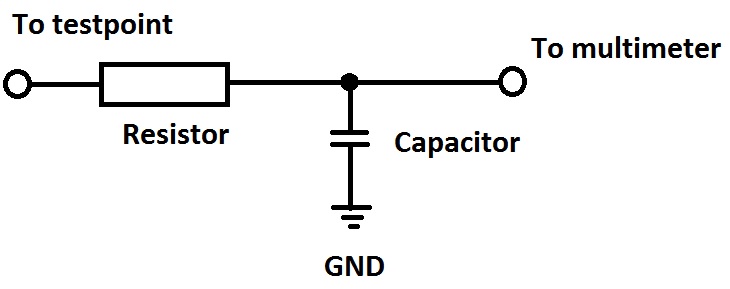
But even with no signals applied there are reasonably fast signals on the video lines, those may fool your multimeter, for this reason we need that adaptor which would be a simple low pass filter actually, so it would give the average of the fast signals, but that would be still OK for us since if we can catch the brightness drift it would shift the measured average value as well -at least his is the plan 
It would need a tiny bit of soldering and a lone capacitor and resistor, their value is not critical at the moment tell me what you have and we put together something useful out of it.
| Description: |
|
| Filesize: |
26.08 KB |
| Viewed: |
9289 Time(s) |
|
_________________
projectors in the past : NEC 6-9PG xtra, Electrohome Marquee 6-7500, NEC XG 1351 LC ( with super modified Electrohome VNB neckboard !!!)
current: VDC Marquee 9500LC
The MOD: VNB-DB, VIM-DB
|
|
| Back to top |
|
|
cynix
Joined: 12 Oct 2009
Posts: 39
Location: Scotland
|
| Posted: Tue Aug 29, 2017 9:47 pm Post subject: |
|
|
When the brightness changes I don't notice any other change. Just tried a quick test there with the "Cross-fine" test pattern at power up and later after the brightness had drifted up and didn't notice any difference with the test pattern, at least not anything more than you'd expect from the normal warm up.
The rest of my setup is an ISCAN VP50 Pro scaler (output set at 1080p48) into the Moome HDMI card on the projector. Source is either a WDTV live streamer or Oppo BDP-83 Blu-ray player. For now I'm testing with the WDTV live.
I do have a 'scope, a PC (USB) Picoscope, but it's not in the same room as the projector and I don't have a fast enough laptop to use it. If there's something crucial to test with the 'scope maybe I can borrow a laptop or something.
I have some 10K resistors and 10v 100uF caps from a mod. chip I made for region hack on Sony DVD player a long time ago (simple RC filter to give analogue voltage output via PWM on PIC microcontroller). If those are not suitable I can get anything else in local electronics shop no problem. Soldering is no problem, I've fitted 1000's of mod chips over the years. Like I said I'm a software guy (with limited hardware knowledge), if this could be fixed with a hack of the firmware I'd be on it already.
Thanks!
|
|
| Back to top |
|
|
gregstv
Joined: 27 Aug 2007
Posts: 628
Location: Australia
|
| Posted: Wed Aug 30, 2017 6:21 am Post subject: |
|
|
|
With the VP50 try 817p@72. This worked really well on my NEC when I was using it.
|
|
| Back to top |
|
|
gjaky
Joined: 05 Jun 2010
Posts: 2802
Location: Budapest, Hungary
|
| Posted: Wed Aug 30, 2017 8:26 pm Post subject: |
|
|
10k and 100uF is great! So do the above mentioned filter and measure the TP7011 on GAIN CTL, and see if it changes with the brightness drift.
_________________
projectors in the past : NEC 6-9PG xtra, Electrohome Marquee 6-7500, NEC XG 1351 LC ( with super modified Electrohome VNB neckboard !!!)
current: VDC Marquee 9500LC
The MOD: VNB-DB, VIM-DB
|
|
| Back to top |
|
|
cynix
Joined: 12 Oct 2009
Posts: 39
Location: Scotland
|
| Posted: Wed Aug 30, 2017 9:41 pm Post subject: |
|
|
OK, done.
Cold start a little dark so correct by enter/exit brightness menu and TP7011 is at 0.570v with black screen.
Check after 40 mins and brightness has drifted way too high, TP7011 now at 0.562v , correct brightness by enter/exit brightness menu and it's still at 0.562v
Thanks!
|
|
| Back to top |
|
|
gjaky
Joined: 05 Jun 2010
Posts: 2802
Location: Budapest, Hungary
|
| Posted: Sat Sep 02, 2017 10:15 am Post subject: |
|
|
OK, Let's see what's on R7437R (VIDEO OUT) with this filter+DMM, you can measure either leg of the resistor.
_________________
projectors in the past : NEC 6-9PG xtra, Electrohome Marquee 6-7500, NEC XG 1351 LC ( with super modified Electrohome VNB neckboard !!!)
current: VDC Marquee 9500LC
The MOD: VNB-DB, VIM-DB
|
|
| Back to top |
|
|
cynix
Joined: 12 Oct 2009
Posts: 39
Location: Scotland
|
| Posted: Sun Sep 03, 2017 8:03 pm Post subject: |
|
|
OK, done.
This was a little harder to test 'cause the reading seemed to be slowly dropping by 0.001v steps over time, even on just the black screen.
From cold start I corrected the brightness and left it on black screen to settle. After 30 mins brightess way too high and reading has settled at 2.677v , correct brightness by enter/exit menu and after removing all on screen display to return to pure black screen reading only drops to 2.675v
The reading seems to work OK as even with on screen display from WDTV on black screen the reading jumped up more than the 0.002v change.
So it seems that the brightness drift isn't present at this test point either?
Happy to test any other points you think are worth checking.
Thanks!
|
|
| Back to top |
|
|
cynix
Joined: 12 Oct 2009
Posts: 39
Location: Scotland
|
| Posted: Mon Sep 04, 2017 3:38 pm Post subject: |
|
|
With another test, now I don't think this setup is sensitive enough to see the brightness change.
Once it had settled down I corrected brightness with menu and waited for OSD to switch off. Then raised brightness manually by +20 (about the same effect as the drift) , waited for OSD to switch off and checked reading. Both values were the same, so it seems this method can't detect the difference in brightness.
I'll see if I can get the 'scope hooked up to it , I think the old laptop I have may be OK for just a snapshot sample.
|
|
| Back to top |
|
|
gjaky
Joined: 05 Jun 2010
Posts: 2802
Location: Budapest, Hungary
|
| Posted: Wed Sep 06, 2017 7:31 pm Post subject: |
|
|
| cynix wrote: | With another test, now I don't think this setup is sensitive enough to see the brightness change.
Once it had settled down I corrected brightness with menu and waited for OSD to switch off. Then raised brightness manually by +20 (about the same effect as the drift) , waited for OSD to switch off and checked reading. Both values were the same, so it seems this method can't detect the difference in brightness.
I'll see if I can get the 'scope hooked up to it , I think the old laptop I have may be OK for just a snapshot sample. |
Indeed the best would be to use an oscilloscope, however the brightness is ultimately set through the G2 lines, but there are different subsetting those affect the two video boards. I was interested in their stability.
There is one thing you haven't measured yet: the actual G2 voltages, but this is dangerous on the first hand, and second it would need a special high impedance high voltage probe as the source impedance is 3MOhm if I recollect right.
_________________
projectors in the past : NEC 6-9PG xtra, Electrohome Marquee 6-7500, NEC XG 1351 LC ( with super modified Electrohome VNB neckboard !!!)
current: VDC Marquee 9500LC
The MOD: VNB-DB, VIM-DB
|
|
| Back to top |
|
|
|
|
|
|
|
You cannot post new topics in this forum
You cannot reply to topics in this forum
You cannot edit your posts in this forum
You cannot delete your posts in this forum
You cannot vote in polls in this forum
You cannot attach files in this forum
You can download files in this forum
|
Forum powered by phpBB © phpBB Group
|
|


