| Author |
Message |
draganm
Joined: 08 Mar 2006
Posts: 8990
Location: Colorado
|
| Posted: Fri Sep 23, 2016 4:38 pm Post subject: |
|
|
try tapping that twisted transistor on the bottom left corner very gently with the tip of a pencil. It could have developed a microscopic crack when it was tightened down.
Next step, do the same to the primary buffering amplifier and whatever that black lump is on top if it (under the glue). Bottom right corner, above socket connector
|
|
| Back to top |
|
 |
gravymaker
Joined: 01 Dec 2006
Posts: 58
Location: Winnipeg
|
|
| Back to top |
|
|
draganm
Joined: 08 Mar 2006
Posts: 8990
Location: Colorado
|
| Posted: Sun Sep 25, 2016 5:10 pm Post subject: |
|
|
|
that SMD capacitor you have circled, C49 , looks burnt by a soldering iron. I would replace this , according to the manual it's an X7R ceramic chip, 470N -50Volt 20% accuracy.
|
|
| Back to top |
|
|
gravymaker
Joined: 01 Dec 2006
Posts: 58
Location: Winnipeg
|
| Posted: Sun Sep 25, 2016 5:35 pm Post subject: |
|
|
Yeah C49 looked suspect to me too. Thanks a ton for the specs.
You might be onto something with the buffering amplifier. When I tapped the transistor, nothing changed. but when I touched/tapped the buffering amp or the component soldered on top of it with a plastic adjustment tool, the tube snapped to life immediately.
I"ll try reflowing the pins on the buffering amp next time it cuts out - for some reason it's been behaving itself for the past couple of days.
_________________
-Scott
|
|
| Back to top |
|
|
draganm
Joined: 08 Mar 2006
Posts: 8990
Location: Colorado
|
| Posted: Mon Sep 26, 2016 4:42 am Post subject: |
|
|
| gravymaker wrote: | | I"ll try reflowing the pins on the buffering amp next time it cuts out -. |
can get to it under all that glue-gunk?
|
|
| Back to top |
|
|
barclay66

Joined: 27 Jun 2011
Posts: 1304
Location: Germany
TV/Projector: Marquee 9500 Ultra
|
| Posted: Mon Sep 26, 2016 10:40 am Post subject: |
|
|
Hi,
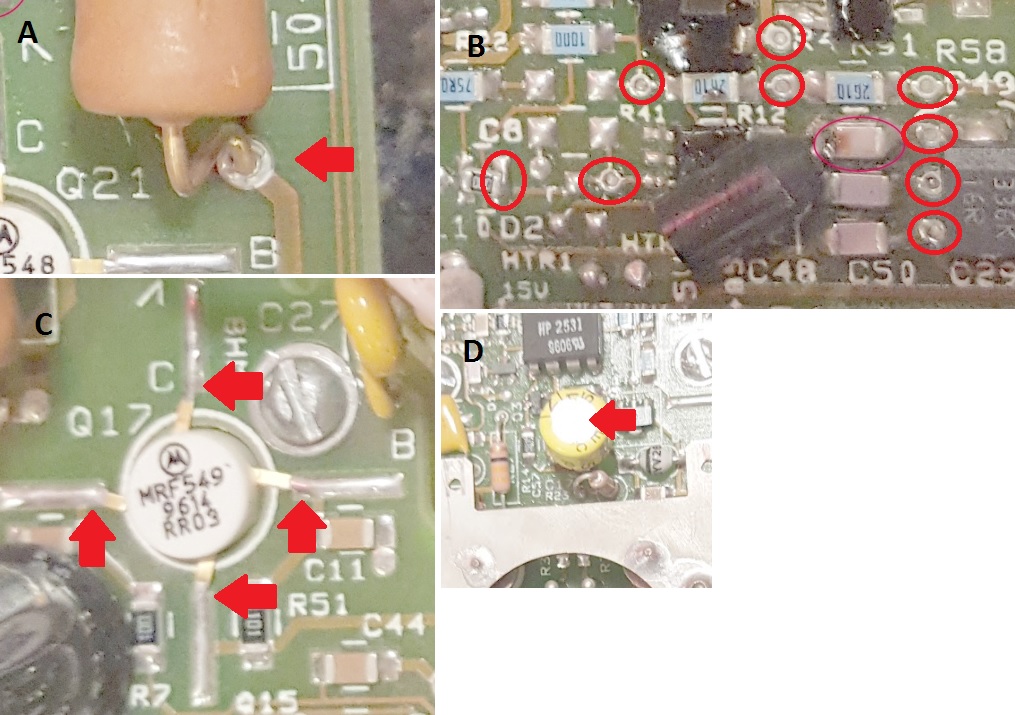
After inspection of the picture You posted, I would recommend resoldering all of the following locations:
Picture A: Big resistor leads (all for of the two resistors)
Picture B: The zero ohm resistor to the left and the red circled plated through-holes
Picture C: The legs of transistor Q17; at least it will relieve the mechanical stress from them
Picture D: The modded output capacitor C17; the replacement cap is so large that it covers the soldering points
Use high-quality solder. I prefer leaded solder (e.g. Sn60Pb39Cu1 with 3.5% HF32 flux) as it produces soldering connections that withstand more mechanical stress than lead-free alternatives.
Regards,
barclay66
| Description: |
|
| Filesize: |
212.56 KB |
| Viewed: |
10427 Time(s) |
|
|
|
| Back to top |
|
|
gravymaker
Joined: 01 Dec 2006
Posts: 58
Location: Winnipeg
|
| Posted: Mon Sep 26, 2016 12:50 pm Post subject: |
|
|
Thanks Barclay, really appreciate the detailed review.
_________________
-Scott
|
|
| Back to top |
|
|
gravymaker
Joined: 01 Dec 2006
Posts: 58
Location: Winnipeg
|
|
| Back to top |
|
|
barclay66
Joined: 27 Jun 2011
Posts: 1304
Location: Germany
TV/Projector: Marquee 9500 Ultra
|
| Posted: Mon Sep 26, 2016 1:40 pm Post subject: |
|
|
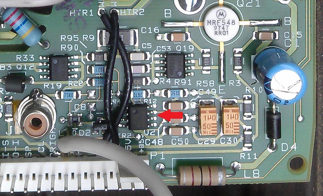
Yes. It's the 8-pin IC (U2) below that big thingy (whatever this is). Below You have a picture of a stock board for reference...
Regards,
barclay66
| Description: |
|
| Filesize: |
145.74 KB |
| Viewed: |
10412 Time(s) |
|
|
|
| Back to top |
|
|
cmjohnson

Joined: 03 Apr 2006
Posts: 5180
Location: Buried under G90s
|
| Posted: Mon Sep 26, 2016 2:02 pm Post subject: |
|
|
If the intermittent connection is on a component covered by black epoxy....this is why you don't cover components in black epoxy. If you've made secret changes to the components, scrape the ID numbers off the parts if you must, but once you epoxy over the parts you've made that board unrepairable in the event of a failure of any covered part.
It's not like anybody is in any mad rush to copy Mike's mods anyway. The market for that just isn't there.
|
|
| Back to top |
|
|
draganm
Joined: 08 Mar 2006
Posts: 8990
Location: Colorado
|
| Posted: Mon Sep 26, 2016 5:17 pm Post subject: |
|
|
| barclay66 wrote: | Yes. It's the 8-pin IC (U2) below that big thingy (whatever this is). Below You have a picture of a stock board for reference...
Regards,
barclay66 |
Wow that"s a nice picture, must be 5 jillion megapixels?  what camera produces that kind of macro image? what camera produces that kind of macro image?
| cmjohnson wrote: | | If the intermittent connection is on a component covered by black epoxy....this is why you don't cover components in black epoxy. |
The other issue is cooling, your effectively insulating the component and trapping all the heat.
|
|
| Back to top |
|
|
gravymaker
Joined: 01 Dec 2006
Posts: 58
Location: Winnipeg
|
| Posted: Mon Sep 26, 2016 5:28 pm Post subject: |
|
|
| Quote: | | The other issue is cooling, your effectively insulating the component and trapping all the heat. |
No kidding - that's a beautiful pic of the VNB!
Speaking of cooling, do you guys run with the Marquee neck cages on or off? I recall a thread (maybe on AVS) where some folks recommended running with the cages off, but I can't seem to find that thread.
_________________
-Scott
|
|
| Back to top |
|
|
draganm
Joined: 08 Mar 2006
Posts: 8990
Location: Colorado
|
| Posted: Mon Sep 26, 2016 5:49 pm Post subject: |
|
|
| gravymaker wrote: | | Quote: | | The other issue is cooling, your effectively insulating the component and trapping all the heat. |
No kidding - that's a beautiful pic of the VNB!
Speaking of cooling, do you guys run with the Marquee neck cages on or off? I recall a thread (maybe on AVS) where some folks recommended running with the cages off, but I can't seem to find that thread. |
On,
The cooling system was designed with a specific amount of back-pressure to all 3 tubes/VNB"s + the HDM and Focus card cages.
changing one will just degrade the others
|
|
| Back to top |
|
|
barclay66
Joined: 27 Jun 2011
Posts: 1304
Location: Germany
TV/Projector: Marquee 9500 Ultra
|
| Posted: Mon Sep 26, 2016 6:29 pm Post subject: |
|
|
| draganm wrote: | | Wow that"s a nice picture, must be 5 jillion megapixels? what camera produces that kind of macro image? |
The full picture shows the entire neck board and was taken by our fellow member tschaeikaei using his HTC Sensation XE. The original file has 8 megapixels. I reused it as I didn't find anything else showing the input section in detail. I won't take false credit for the acheivement of others 
|
|
| Back to top |
|
|
barclay66
Joined: 27 Jun 2011
Posts: 1304
Location: Germany
TV/Projector: Marquee 9500 Ultra
|
| Posted: Mon Sep 26, 2016 6:35 pm Post subject: |
|
|
| gravymaker wrote: | | Speaking of cooling, do you guys run with the Marquee neck cages on or off? I recall a thread (maybe on AVS) where some folks recommended running with the cages off, but I can't seem to find that thread. |
In addition to the mechanical properties, the cage also provides shielding against external RF interference. Remember: The boards on the large heat sink face directly onto the neck boards. And they truly produce RF noise...
Last edited by barclay66 on Mon Sep 26, 2016 7:03 pm; edited 1 time in total
|
|
| Back to top |
|
|
cmjohnson
Joined: 03 Apr 2006
Posts: 5180
Location: Buried under G90s
|
| Posted: Mon Sep 26, 2016 6:37 pm Post subject: |
|
|
Some of you may be interested to know that the split pack Marquees ran with neck cages that have fans in them. They also run with no plastic tube covers and there is a clamp assembly the neck card cage is mounted to. It clamps to the tube neck. It's actually a repurposed original AmPro part with an extra bracket on it.
Dumb me, I could once have had a small pile of them for free but I didn't recognize what they were!
The fans are not noisy. They're a nice solution if you want assured cooling and also want the RF shielding attribute that the full
neck card cage and cover assembly provides.
VDC has the required parts. One thing you also need is the fan power distribution board. It gets its power from the backplane board and has connectors for the cage fans.
|
|
| Back to top |
|
|
draganm
Joined: 08 Mar 2006
Posts: 8990
Location: Colorado
|
| Posted: Wed Sep 28, 2016 5:37 pm Post subject: |
|
|
| cmjohnson wrote: | Some of you may be interested to know that the split pack Marquees ran with neck cages that have fans in them. They also run with no plastic tube covers and there is a clamp assembly the neck card cage is mounted to. It clamps to the tube neck. It's actually a repurposed original AmPro part with an extra bracket on it.
|
that makes sense, if you take the plastic off no air could be ducted back the the VNB cage, hence the little fan
|
|
| Back to top |
|
|
gravymaker
Joined: 01 Dec 2006
Posts: 58
Location: Winnipeg
|
| Posted: Mon Oct 03, 2016 12:56 am Post subject: |
|
|
Well guys, it sure looks like we've narrowed it down to this component that was soldered above the buffering amp... i tried removing it and re-soldering it, and even removing it completely from the board in desperation, but no luck.
Pretty sure its this component that's failed, based on the troubleshooting to date. I've reached the end of my patience, though. Likely someone with some knowledge could fix this in a jiffy.
Does anyone have a spare marquee neckboard for sale? I'd gladly send you this MP-modded neckboard in exchange - perhaps someone with real knowledge would get it going.
_________________
-Scott
|
|
| Back to top |
|
|
draganm
Joined: 08 Mar 2006
Posts: 8990
Location: Colorado
|
| Posted: Mon Oct 03, 2016 5:04 pm Post subject: |
|
|
|
I think I have some MP neck-boards here, no idea which version, but older. $50. shipped to you in Canada for 1, $75. for both
|
|
| Back to top |
|
|
gravymaker
Joined: 01 Dec 2006
Posts: 58
Location: Winnipeg
|
| Posted: Mon Oct 03, 2016 6:38 pm Post subject: |
|
|
Thanks - sent you a pm with contact info.
_________________
-Scott
|
|
| Back to top |
|
|
|
|


