| Author |
Message |
the dude
Joined: 11 Sep 2013
Posts: 179
|
| Posted: Tue Feb 09, 2016 11:29 pm Post subject: Barco 909 Neckboards in 1209s! |
|
|
Hi Folks,
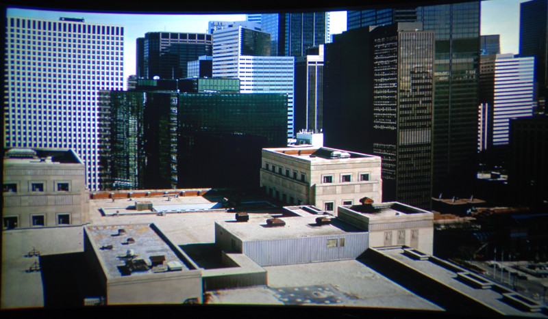
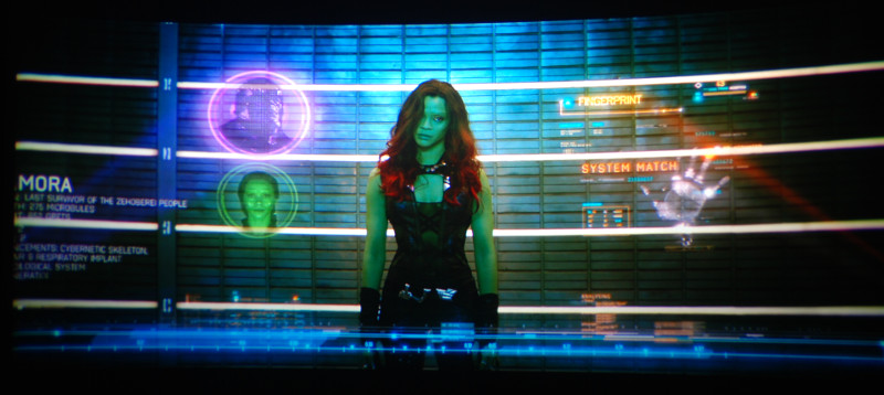
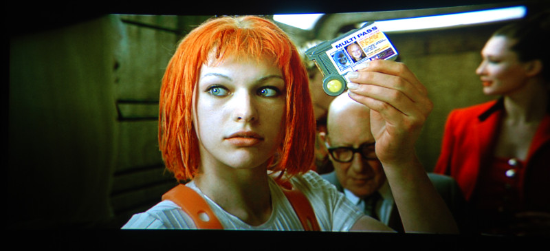
last weekend i managed to install Barco 909 neckboards in my 1209s! Since the ABL and blanking signal and supply voltages are exactly the same this was easier than expected. Only G2 voltage supply was an issue. The picture with the 909 boards ist really stunning  I also replaced the HFA1100 Op Amps on the switcher and RGB driver board with THS3201 (1.8 Ghz) a while ago, so now my set should have more bandwith than a stock 909. Unfortunally i don't have the proper equipment to prove that. I also replaced the HFA1100 Op Amps on the switcher and RGB driver board with THS3201 (1.8 Ghz) a while ago, so now my set should have more bandwith than a stock 909. Unfortunally i don't have the proper equipment to prove that.
If anyone is interessted in this stuff, i could try to document how this can be done. In fact the only board that must be modified slightly is the G2/Diagnostic board.
Some screenshoots:
| Description: |
|
| Filesize: |
152.08 KB |
| Viewed: |
12467 Time(s) |
|
| Description: |
|
| Filesize: |
89.77 KB |
| Viewed: |
12467 Time(s) |
|
| Description: |
|
| Filesize: |
73.48 KB |
| Viewed: |
12467 Time(s) |

|
| Description: |
|
| Filesize: |
76.22 KB |
| Viewed: |
12467 Time(s) |
|
| Description: |
|
| Filesize: |
102.83 KB |
| Viewed: |
12467 Time(s) |
|
|
|
| Back to top |
|
 |
Nashou66

Joined: 12 Jan 2007
Posts: 16171
Location: West Seneca NY
|
|
| Back to top |
|
|
km987654

Joined: 25 Jul 2007
Posts: 2874
Location: Australia
TV/Projector: Barco BG809s
|
| Posted: Wed Feb 10, 2016 1:11 am Post subject: |
|
|
Documenting these mods would be great. Look forward to it. 
Screen shots don't always convey the improvement. What would you describe as the differences?
|
|
| Back to top |
|
|
dummyload
Joined: 06 Apr 2006
Posts: 38
Location: belgium
|
| Posted: Wed Feb 10, 2016 7:46 am Post subject: |
|
|
|
Not to spoil the party but the hfa1100 is not the problem (bandwidth wise) ,on the switcher and driverboard.
|
|
| Back to top |
|
|
km987654
Joined: 25 Jul 2007
Posts: 2874
Location: Australia
TV/Projector: Barco BG809s
|
| Posted: Wed Feb 10, 2016 9:03 am Post subject: |
|
|
| dummyload wrote: | | Not to spoil the party but the hfa1100 is not the problem (bandwidth wise) ,on the switcher and driverboard. |
Ok so come clean what is the problem? 
|
|
| Back to top |
|
|
mp20748
Joined: 12 Sep 2006
Posts: 5689
Location: Maryland
TV/Projector: 9500LC Ultra / Super 02 and 03 VIM
|
| Posted: Wed Feb 10, 2016 9:56 am Post subject: |
|
|
| dummyload wrote: | | Not to spoil the party but the hfa1100 is not the problem (bandwidth wise) ,on the switcher and driverboard. |
what do you recommend changing for improved bandwidth?
|
|
| Back to top |
|
|
dummyload
Joined: 06 Apr 2006
Posts: 38
Location: belgium
|
| Posted: Wed Feb 10, 2016 11:09 am Post subject: |
|
|
what I mean is that the bandwidth of a circuit is determines by the component with the lowest value.
In this case it is the ad835 that has a -3db at 250mhz and there are two in serie so even that number will be lower, so there will be little difference replacing a 850mhz opamp in the chain with a 1,3ghz one. The sony g90 also uses the ad835 and also lacks bandwidth ,the marquee doesn't use the ad835 but uses the ad834 which has -3db at 500mhz and that's why the marquee can be moded and tuned to the level it is at now. The only way to get a real difference in bandwith is to replace ad835 with ad834 but there lies the problem they are not compatible components ,so the circuit has to be changed significantly and there are 7 of them in total in the chain (switcher and driver) and then all opamps have to be tuned to get max bandwidth . And then you still have to deal with the neckboard wich is a total different animal.
In dude case the neckboard of the 909 made the difference I think.
MP you already know this.
|
|
| Back to top |
|
|
hansilili

Joined: 09 Mar 2007
Posts: 302
Location: Köln, Germany
|
| Posted: Wed Feb 10, 2016 11:11 am Post subject: |
|
|
Hey Dude,
a guy in another forum I'm active in (aka rumpeli) is thinking (phantasizing) about upgrading his 1209s to a 909. In Germany that still means massive invest. How would you rate the upgrade.
Offtopic but much more intreisting to me - give us some more details about your apparently curved screen. Can you post some pics of your built in the "Home Theater Design & Construction" board?
Thanks
_________________
HansA, alles andere ist euer Bier!
|
|
| Back to top |
|
|
mp20748
Joined: 12 Sep 2006
Posts: 5689
Location: Maryland
TV/Projector: 9500LC Ultra / Super 02 and 03 VIM
|
| Posted: Wed Feb 10, 2016 12:17 pm Post subject: |
|
|
| dummyload wrote: | what I mean is that the bandwidth of a circuit is determines by the component with the lowest value.
In this case it is the ad835 that has a -3db at 250mhz and there are two in serie so even that number will be lower, so there will be little difference replacing a 850mhz opamp in the chain with a 1,3ghz one. The sony g90 also uses the ad835 and also lacks bandwidth ,the marquee doesn't use the ad835 but uses the ad834 which has -3db at 500mhz and that's why the marquee can be moded and tuned to the level it is at now. The only way to get a real difference in bandwith is to replace ad835 with ad834 but there lies the problem they are not compatible components ,so the circuit has to be changed significantly and there are 7 of them in total in the chain (switcher and driver) and then all opamps have to be tuned to get max bandwidth . And then you still have to deal with the neckboard wich is a total different animal.
In dude case the neckboard of the 909 made the difference I think.
MP you already know this. |
In theory you are correct, but my experience wit the AD835 is very different. I have been able to get it to handle up to 300mhz, but a lot of that has to do with the circuit configuration. The 02 VIM I'm using it in right now (the Maquee has two different video input modules, one has the AD834 and the other AD835).
It's difficult to look at the video chain and say what should be happening from my experience. For instance, the Barco that we're talking about as quite a few of the AD835 in it's video chain. Barco uses three for gain, which makes sense because you'll need a gain amplifier. But then they add a second AD835 for Gamma adjustment. Not sure what they had in mind, but the G90 does something very similar with this gamma adjustment feature for more than just blue. Anyway, this could be a bottleneck, and that's why I removed the gamma AD835 when I was modifying the 909.
Sometimes the signal maintains integrity going through the video chain at higher bandwidth requirements, and sometimes it's really hindered. But the only way to know is the literally see what's happening using good forms of testing.
I know the bottlenecks in the 909. There's also one on the neck boards
|
|
| Back to top |
|
|
dummyload
Joined: 06 Apr 2006
Posts: 38
Location: belgium
|
| Posted: Wed Feb 10, 2016 1:30 pm Post subject: |
|
|
@mp
I agree rf is a game apart , theory and practice can vary big time ,everything affects the outcome (quantity of soldering ,for example) and reliable measuring is also tricky. By the way , very nice job on the marquee.
|
|
| Back to top |
|
|
mp20748
Joined: 12 Sep 2006
Posts: 5689
Location: Maryland
TV/Projector: 9500LC Ultra / Super 02 and 03 VIM
|
| Posted: Wed Feb 10, 2016 2:10 pm Post subject: |
|
|
| dummyload wrote: | @mp
I agree rf is a game apart , theory and practice can vary big time ,everything affects the outcome (quantity of soldering ,for example) and reliable measuring is also tricky. By the way , very nice job on the marquee. |
Thank you.. and make sure you continue to contribute, you seem to know a bunch that can be very helpful to others.
|
|
| Back to top |
|
|
the dude
Joined: 11 Sep 2013
Posts: 179
|
| Posted: Wed Feb 10, 2016 6:24 pm Post subject: |
|
|
Let me try to give some answers...
THS3201 vs. HFA1100
I know that this isn't the bottleneck. The real bottleneck was the neckboards for sure, and then the gain control multiplier AD835. But the op amps are much easier to replace since the THS3201 is pin compatible and very similar except for better bandwidth and much better rise time. Thats the reason for replacing it first. The "only" problem was to get rid of the oscillations, this was much harder than expected.
Gain Control AD835
I plan to replace this, but this is more complicated. I have ordered ADL5391 also, but was scared away just by the size of the package I plan to make a very tiny pcb with this chip on it some day to replace the AD835, but that would not be easy. The soldering really scares me. I think i need a microscope or there is no hope for it.
Gamma corrector AD835
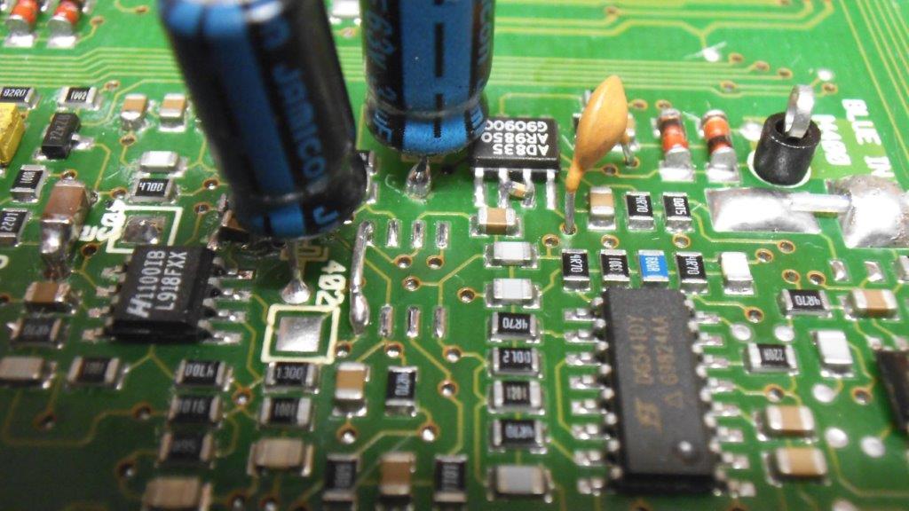
I believe the second AD835 (I203/I403) is not an issue. In fact it is not in series with the signal, it just applies a litte of the video signal multiplied with itself to the inverting input of the second op amp (I204/I404). So even if this signal is missing completly, gamma will be slightly off but no information in the image is missing. You don't really need gamma correction on fine structures, if this stage forms a lowpass you loose almost no quality in my opinion. Different frequency responses may introduce some ringing here, but i believe that is barely visible. I would keep this stage as it is. Especially with the stray capacitance in mind that a replacement circuit that is mechnical just a litte bit larger would cause on the inverting input of the current op amp (stabilty issues, this is *VERY* critical). Also the inverting input of a CFA is current driven, so the output impedance of this multiplier may also be critical. Maybe not. Just keep it, it only equalizes the gamma response of the different phosphor types for the individual colors.
THS3201 and oscillations
I had issues with that on the rgb driver board and it took days to get rid of it. A combination of this did the trick:
- playing with the feedback resistor network (this sets gain AND bandwidth)
- adding a rc lowpass to the output (between the output and the load, of course the fb resistor need to be connected straigt). It was something like 25pf / 4,7 Ohm, i don't remember the actual values, i tried many things. But i have noticed them somewhere. It is important to place the series resistor as close as possible to the output lead, there should not even be a milimeter of pcb track between the output and the resistor.
- Removing parts of the groundplane (not sure if this is really helpfull, it was just a idea i tried)
- And finally most important: Removal of ANY peaking component. Its a bad idea to add a capacitor to the inverting input of a cfa like barco did. This is a NO GO.
Maybe some of this is bull**** - im not an expert for CFAs, but it worked for me.
The Screen
Yes, its curved. Its a Kappa Line board painted with aluminium paint.
The image quality with the 909 boards
Well, its hard to be objective without a direct A/B comparsion. In general i would say the image is sharper in general. Also it seems to look cleaner than before, i guess this is because of massive peaking of the original VPH08. Remember, this video pack was rated for 85 Mhz only and Barco added a lot of peaking! And there seem to be slightly more details visible in darker areas (this may be a subjective impression, but i think so). Maybe because because ABL is done via G2 and G2 is more precise now? With the old boards there was a quite visible difference between 1080p48 and 1080p60. Now 1080p60 is almost as sharp as 1080p48.
I will try to explain how to replace the neckboards soon, stay tuned!
|
|
| Back to top |
|
|
mp20748
Joined: 12 Sep 2006
Posts: 5689
Location: Maryland
TV/Projector: 9500LC Ultra / Super 02 and 03 VIM
|
| Posted: Wed Feb 10, 2016 9:25 pm Post subject: |
|
|
| the dude wrote: |
Gamma corrector AD835
I believe the second AD835 (I203/I403) is not an issue. In fact it is not in series with the signal, it just applies a litte of the video signal multiplied with itself to the inverting input of the second op amp (I204/I404). So even if this signal is missing completly, gamma will be slightly off but no information in the image is missing. You don't really need gamma correction on fine structures, if this stage forms a lowpass you loose almost no quality in my opinion. Different frequency responses may introduce some ringing here, but i believe that is barely visible. I would keep this stage as it is. Especially with the stray capacitance in mind that a replacement circuit that is mechnical just a litte bit larger would cause on the inverting input of the current op amp (stabilty issues, this is *VERY* critical). Also the inverting input of a CFA is current driven, so the output impedance of this multiplier may also be critical. Maybe not. Just keep it, it only equalizes the gamma response of the different phosphor types for the individual colors |
The gamma AD835 is not directly in-line of the video path, but its direct connection to the 1100 is not good for the best video quality we're expecting from these projectors. Also, having a difference as such will affect the overall image, because it's very important that each of the three video signals remain as equal as possible thru-out the entire video chain and with it in there, it affects the video linearity that's so important for HD depth and 2D effect. That gamma circuit was added for a sheer hyped (selling) feature. I doubt if it was ever used.
It's really best to remove them. And when you do simply connect PIN 5 on the IC trace to ground.
| Quote: | | THS3201 and oscillations |
Why even bother with that chip, knowing they're easy to oscillate. And even when you tame them, because of their extreme bandwidth capability, they still oscillate to some degree. The goal in using high bandwidth chips for video, is to make sure you have a good bandwidth ceiling, but you also have to make sure you don't exceed that ceiling. Not all claimed high bandwidth video chips are good for good video quality and clean operation. Another problem with these HB chips their oscillation is usally so subdued that it plays out as a slight film or layer in the image. The Comlinear chips were famous for this (CLCXXX).
Use something tried and true like the Intersil EL5166 or any of those 1400mhz and below chips. Stay away from those Super chips.
The BOTTLENECK on the neck drive boards is the OPA688 Top/Bottom clamp IC. It needs to be removed. It's only purpose is another useless hyped selling feature that allows an adjustment of white (top) and black (bottom) clamp or removal from image. Really totally useless for modern day HD
|
|
| Back to top |
|
|
redfox001

Joined: 16 Mar 2009
Posts: 2257
Location: The Netherlands
|
| Posted: Wed Feb 10, 2016 11:08 pm Post subject: |
|
|
There are ADL5391 breakout boards see google (LFCSP breakout). Perhaps with one of those you can make a miniboard mod?
_________________
701s->runco933->8500ultra->cinemax->9500mp->919 splitpack + cinemax
|
|
| Back to top |
|
|
the dude
Joined: 11 Sep 2013
Posts: 179
|
| Posted: Wed Feb 10, 2016 11:25 pm Post subject: |
|
|
| Quote: |
The BOTTLENECK on the neck drive boards is the OPA688 Top/Bottom clamp IC. It needs to be removed. It's only purpose is another useless hyped selling feature that allows an adjustment of white (top) and black (bottom) clamp or removal from image. Really totally useless for modern day HD |
Good point! I also noticed this, but assumed there is a good reason for it. Putting a voltage feedback op amp in the chain just for clamping adjustment seems to be a bad thing. Nobody ever touches these pots... However, i just figured out the boards can be used, optimizing them would be the next step 
| Quote: |
There are ADL5391 breakout boards see google. Perhaps with one of those you can make a miniboard mod?
|
I only know the evaluation board, but this is to big... But anyway, a making a circuit board isn't that hard, but soldering this chip is a nightmare...
Edit: Now i got it... hm, anyway i have to match the layout of the board, and wires are a bad idea.
|
|
| Back to top |
|
|
redfox001
Joined: 16 Mar 2009
Posts: 2257
Location: The Netherlands
|
| Posted: Thu Feb 11, 2016 4:50 am Post subject: |
|
|
Small wires to input and output are no problem with the ad835. The soldering can be done with a small tip and flux. Or hot air station.
But you have to add some decoupling caps somewhere. Perhaps connect the breakout to a small experimentation print?
_________________
701s->runco933->8500ultra->cinemax->9500mp->919 splitpack + cinemax
|
|
| Back to top |
|
|
gregstv
Joined: 27 Aug 2007
Posts: 628
Location: Australia
|
| Posted: Thu Feb 11, 2016 7:00 am Post subject: |
|
|
I removed the Gamma chips a while ago. Added a jumper from pin 4 to pin 5. This helped reduce noise. Noticeable on the blue mainly.
I also added a 22pf cap from Pin 8 to ground (gain control) on the AD835. This reduced the noise level quite a lot on the 808s.
There are a few other changes I made that also helped. They are listed in the SEOS thread.
I have some mods on the Focus Astig board that SEOS have done by the looks of it. 3 SEOS boards and all have a cap in series with a resistor from the output pins on the STK chips to ground. I will post more on this if anyone is interested.
| Description: |
|
| Filesize: |
98.65 KB |
| Viewed: |
12155 Time(s) |
|
|
|
| Back to top |
|
|
km987654
Joined: 25 Jul 2007
Posts: 2874
Location: Australia
TV/Projector: Barco BG809s
|
| Posted: Thu Feb 11, 2016 7:36 am Post subject: |
|
|
Hey Greg
So did SEOS modify the H-Shift and focus board?
|
|
| Back to top |
|
|
gregstv
Joined: 27 Aug 2007
Posts: 628
Location: Australia
|
| Posted: Thu Feb 11, 2016 10:28 am Post subject: |
|
|
Hi Keith,
I have boards that are different revisions. I haven't seen anything that looks modified.
Greg.
|
|
| Back to top |
|
|
redfox001
Joined: 16 Mar 2009
Posts: 2257
Location: The Netherlands
|
|
| Back to top |
|
|
|
|


