| Author |
Message |
the dude
Joined: 11 Sep 2013
Posts: 179
|
| Posted: Tue Feb 23, 2016 8:32 pm Post subject: |
|
|
Nice Scope 
To get a real square wave you need to solder the probe to the PCB.
Trigger: You scope should let you choose the signal it triggers on. Look for the Trigger source selector. You can make it trigger on chanel 2. Then you connect the H-SYNC to channel 2. You need not to make the chanel active, it can be used for triggering anyway.
Also you can play with trigger level and hold off.
|
|
| Back to top |
|
 |
redfox001

Joined: 16 Mar 2009
Posts: 2257
Location: The Netherlands
|
| Posted: Tue Feb 23, 2016 8:41 pm Post subject: |
|
|
| the dude wrote: | And now something constructive:
We can use HSMP-3832-BLKG for the protection clamp. Its a pin diode (2 diodes in single package) capable of 200V reverse voltage each.
It has only 0,3 pf capacitance per device. At 20V reverse voltage it would only be 0,2 pf!
The diode is available from farnell. |
How much pf are the current diodes? I remember that removing them from the marquee made little difference but that was by eye.
_________________
701s->runco933->8500ultra->cinemax->9500mp->919 splitpack + cinemax
|
|
| Back to top |
|
|
redfox001
Joined: 16 Mar 2009
Posts: 2257
Location: The Netherlands
|
| Posted: Tue Feb 23, 2016 8:45 pm Post subject: |
|
|
| the dude wrote: | Nice Scope
To get a real square wave you need to solder the probe to the PCB.
Trigger: You scope should let you choose the signal it triggers on. Look for the Trigger source selector. You can make it trigger on chanel 2. Then you connect the H-SYNC to channel 2. You need not to make the chanel active, it can be used for triggering anyway.
Also you can play with trigger level and hold off. |
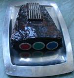
I soldered with two short wires to the connector on the moome on the back.
 Untitled by Radio Head, on Flickr Untitled by Radio Head, on Flickr
_________________
701s->runco933->8500ultra->cinemax->9500mp->919 splitpack + cinemax
|
|
| Back to top |
|
|
redfox001
Joined: 16 Mar 2009
Posts: 2257
Location: The Netherlands
|
| Posted: Tue Feb 23, 2016 8:49 pm Post subject: |
|
|
When I look to this burst the fatter part it actually looks like the digital scope but a lit less roll of. But to much distortion because it was difficult to trigger. Definately some peaking on the moome at 1080p@60.
 Untitled by Radio Head, on Flickr Untitled by Radio Head, on Flickr
 Untitled by Radio Head, on Flickr Untitled by Radio Head, on Flickr
_________________
701s->runco933->8500ultra->cinemax->9500mp->919 splitpack + cinemax
|
|
| Back to top |
|
|
the dude
Joined: 11 Sep 2013
Posts: 179
|
| Posted: Tue Feb 23, 2016 8:51 pm Post subject: |
|
|
| Quote: | | How much pf are the current diodes? |
1.5 pf.
There are 2 in series, but the on 2 rails and this doubles the capacity again. So it would be 1.5 pf load just for the diodes. There should be 4 in series or better ones.
1.5 pf is very low, but since we have about 10-12 pf on the cathode this is something we should optimize. Also the gas discharge protector is in the same range.
|
|
| Back to top |
|
|
the dude
Joined: 11 Sep 2013
Posts: 179
|
| Posted: Tue Feb 23, 2016 8:53 pm Post subject: |
|
|
|
You can see the ringing at top of the signal, so the amplitude can be misleading. In fact this may show the same result!
|
|
| Back to top |
|
|
gjaky
Joined: 05 Jun 2010
Posts: 2802
Location: Budapest, Hungary
|
| Posted: Tue Feb 23, 2016 8:59 pm Post subject: |
|
|
| the dude wrote: |
1.5 pf is very low, but since we have about 10-12 pf on the cathode this is something we should optimize. Also the gas discharge protector is in the same range. |
LUG tubes have lower capacitance! Cathode has about 3pF to other electrodes and G1 has 6pF if KH "grid" is used.
_________________
projectors in the past : NEC 6-9PG xtra, Electrohome Marquee 6-7500, NEC XG 1351 LC ( with super modified Electrohome VNB neckboard !!!)
current: VDC Marquee 9500LC
The MOD: VNB-DB, VIM-DB
|
|
| Back to top |
|
|
the dude
Joined: 11 Sep 2013
Posts: 179
|
| Posted: Tue Feb 23, 2016 9:12 pm Post subject: |
|
|
Huh!
Have i green lug in wrong housing. Very little wear and well useable. The PT22-22 has better phosphor, but that doesn't matter since are are both fine. Maybe i should swap it...
Does this KH grid really reduce capacitance that much? There are very few infos about it, i know this socket diagram with a comment about capacitance.
|
|
| Back to top |
|
|
redfox001
Joined: 16 Mar 2009
Posts: 2257
Location: The Netherlands
|
| Posted: Tue Feb 23, 2016 9:19 pm Post subject: |
|
|
| the dude wrote: | | You can see the ringing at top of the signal, so the amplitude can be misleading. In fact this may show the same result! |
yes seems the same result.
_________________
701s->runco933->8500ultra->cinemax->9500mp->919 splitpack + cinemax
|
|
| Back to top |
|
|
mp20748
Joined: 12 Sep 2006
Posts: 5689
Location: Maryland
TV/Projector: 9500LC Ultra / Super 02 and 03 VIM
|
| Posted: Tue Feb 23, 2016 9:32 pm Post subject: |
|
|
| the dude wrote: | | Quote: | | Has it really sunk in that maybe I'm to only person you know that has been able to get a video chain in a CRT projector to exceed 300Mhz bandwidth? |
Maybe you are the only person in this business who can't tell frequency from samplerate 
You mean 300 Mhz pixel clock?
You should stop this stupid advertisement, thats ridiculous...
And no, that is not a matter of definition. The term "bandwidth" and "sample rate" are well defined. Call your fantasy unit Megamike if you like, buts thats not Megahertz.
https://en.wikipedia.org/wiki/Nyquist%E2%80%93Shannon_sampling_theorem |
LoL.. 
You are really what they call GREEN. That means you seriously lack any real experience, and therefore that would make you a text book only idiot..
Let me go over this again... It's all about RULE. I even went further and stated what Rule I would be using...that is very important, because the bandwidth thing can be very complicated as I had already indicated.
Now the RULE that I was following was the same RULE as Chroma uses (the maker of my industrial generator) and I had posted the screenshot of what it shows on its DISPLAY on my generator. Remember that?
Stay with me now because you're having a real difficult time not using Non-relevant Theory here....If on my display it has an "M" for Bandwidth. And in the manual for the generator, they use "Bandwidth"....and also on the generators website they also use the word Bandwidth for their generators, why If after I stated what RULE I was using to include. IT IS THE SAME RULE THE ENTIRE INDUSTRY USES, please tell me how you can so easily toss aside a very valid and relevant standard used for video displays today. Oh and I understand some of the other rules floating in your head and you're really confused about what I'm talking about because it's so different from your text-book knowledge. And so far you're wrtong again because you are disputing a well known and established RULE. If you're right, every display system, generator, processor, blend unit, etc are using the wrong rule.
Let me help you out here. There are two different pixel resolutions standards in the industry. One is for digital and the other is analog. One is Digital Pixel Bandwidth while the other is Analog Pixel Bandwidth. The one I'm using is Analog Pixel Bandwidth (analog out). On my generator the specs says its analog pixel Bandwidth is 330mhz. It also has an Digital Pixel bandwidth (DVI out), and its rating is 300mhz
So if I'm wrong here, you would have to fault the industry standard that I've been following for which you can't challenge.
| Quote: |
The 2237 is designed with the accurate Phase Lock
Loop (PLL), which can reach 25PPM/1PPM after
calibration and provide video signals for 256 colors
per pixel. It's maximum video frequency is 330MHz
for digital and 360MHz for analog
|
Oh and on that diode discussion, you were wrong again.
And another thing, you guys are really getting off with those burst patterns. What's funny is, the only thing you're looking at on the patterns is the amplitude. There is serious flaws in some of those shots, and you guys keep talking about the amplitude..
Oh one more thing what RULE are you giys using for the burst shots and how do you determine when the bandwidth is right?
Last edited by mp20748 on Tue Feb 23, 2016 9:59 pm; edited 5 times in total
|
|
| Back to top |
|
|
mp20748
Joined: 12 Sep 2006
Posts: 5689
Location: Maryland
TV/Projector: 9500LC Ultra / Super 02 and 03 VIM
|
| Posted: Tue Feb 23, 2016 9:34 pm Post subject: |
|
|
| the dude wrote: | | And of course discussions on SWR related problems with power transistors are interesting for ham radio and have nothing to do with esd or overvoltage protection. |
Unbelievable..
.
|
|
| Back to top |
|
|
the dude
Joined: 11 Sep 2013
Posts: 179
|
| Posted: Tue Feb 23, 2016 9:48 pm Post subject: |
|
|
Couldn't say it better 
|
|
| Back to top |
|
|
redfox001
Joined: 16 Mar 2009
Posts: 2257
Location: The Netherlands
|
| Posted: Tue Feb 23, 2016 9:52 pm Post subject: |
|
|
| the dude wrote: | | Quote: | | How much pf are the current diodes? |
1.5 pf.
There are 2 in series, but the on 2 rails and this doubles the capacity again. So it would be 1.5 pf load just for the diodes. There should be 4 in series or better ones.
1.5 pf is very low, but since we have about 10-12 pf on the cathode this is something we should optimize. Also the gas discharge protector is in the same range. |
Looked up the data sheet it says 5pf!
https://www.fairchildsemi.com/datasheets/BA/BAS21.pdf
_________________
701s->runco933->8500ultra->cinemax->9500mp->919 splitpack + cinemax
|
|
| Back to top |
|
|
the dude
Joined: 11 Sep 2013
Posts: 179
|
| Posted: Tue Feb 23, 2016 9:55 pm Post subject: |
|
|
|
Ups... different manufacers, different performance.
|
|
| Back to top |
|
|
redfox001
Joined: 16 Mar 2009
Posts: 2257
Location: The Netherlands
|
| Posted: Tue Feb 23, 2016 10:01 pm Post subject: |
|
|
| the dude wrote: | | Ups... different manufacers, different performance. |
If this is true it loads more than the tube!
_________________
701s->runco933->8500ultra->cinemax->9500mp->919 splitpack + cinemax
|
|
| Back to top |
|
|
redfox001
Joined: 16 Mar 2009
Posts: 2257
Location: The Netherlands
|
| Posted: Tue Feb 23, 2016 10:02 pm Post subject: |
|
|
| redfox001 wrote: | | I think the videodac can only make a sine from 1 pixel patterns and make the wavy pattern from three pixel patterns. That should be correct. Asymmetry is still strange. |
Asymmetry gone when ground and signal are reverse connected.
_________________
701s->runco933->8500ultra->cinemax->9500mp->919 splitpack + cinemax
|
|
| Back to top |
|
|
the dude
Joined: 11 Sep 2013
Posts: 179
|
| Posted: Tue Feb 23, 2016 10:03 pm Post subject: |
|
|
Mike, i really don't care what they write in your manual or whats on that display.
It is a analog circuit. Period. A analog circuit has no pixelclock or analog pixels (whatever that means). In the analog domain the term "bandwith" means the frequency range where the amplitude is -3db off (otherwise you have to specify rolloff). Thats a the only definiton. It applies to video, audio, everything. Its a common accepted definition for engineering.
|
|
| Back to top |
|
|
the dude
Joined: 11 Sep 2013
Posts: 179
|
|
| Back to top |
|
|
the dude
Joined: 11 Sep 2013
Posts: 179
|
| Posted: Tue Feb 23, 2016 10:59 pm Post subject: |
|
|
Something on the diodes:
It seems i found the only datasheet that says they are 1.5 pf 
Its form PanJit, Taiwan. All other (checked NXP, Infinion, Fairchild, Diodes, Diotec, Transys, Zetex, Siemens) rate them 5 pf at 1 Mhz.
Last edited by the dude on Tue Feb 23, 2016 11:00 pm; edited 1 time in total
|
|
| Back to top |
|
|
mp20748
Joined: 12 Sep 2006
Posts: 5689
Location: Maryland
TV/Projector: 9500LC Ultra / Super 02 and 03 VIM
|
| Posted: Tue Feb 23, 2016 11:00 pm Post subject: |
|
|
Again, when you speak of bandwidth you have to be specific, and that is why the wiki shows "Bandwidth (signal Processing)"
From the same wiki:
| Quote: | This article is about the concept in signal theory and processing measured in hertz. For use in computing and networking expressed in bits per second, see Bandwidth (computing). For other uses, see Bandwidth...
|
The bandwidth as it would relate to a pattern generator and display would be different. That would require PIXELs and/or resolution.
Check out this calculator and what it needs to determine the bandwidth:
http://myhometheater.homestead.com/bandwidthcalculator.html
So when I put in 1920X1440 75HZ the calculated results are: 311mhz
.
|
|
| Back to top |
|
|
|
|