| Author |
Message |
the dude
Joined: 11 Sep 2013
Posts: 179
|
| Posted: Thu Feb 11, 2016 6:56 pm Post subject: |
|
|
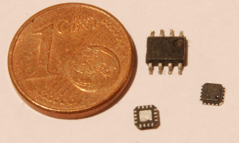
@Greg: Its hard to believe that removing the chip completly won't cause gamma/color balance problems. It would be nice to have this stage eliminated. Are there really no issues without it? That would mean this stage does only very litte corrections that are unnessesary? Good color balance is important to me.
Maybe i do some further tests and investigation this weekend if i find the time.
@Redfox: I can etch a pcb, thats not the problem... Soldering SOIC8 is like shooting a fish in a barrel, but the package of the ADL5391 is a complete different story. It even has no leads but contacs under the package and its recommented to solder the middle contact to the groundplane. I have a hot air station, but for this a reflow oven and a microscope would be desireable.
This is the ADL5391:
| Description: |
|
| Filesize: |
76.53 KB |
| Viewed: |
7099 Time(s) |
|
|
|
| Back to top |
|
 |
Nashou66

Joined: 12 Jan 2007
Posts: 16171
Location: West Seneca NY
|
| Posted: Thu Feb 11, 2016 7:16 pm Post subject: |
|
|
Dude, solder paste and hot is your friend. Apply solder paste across the pads on PCB , even if it gets in between them. then place chip on paste and pads and apply hot air. the solder paste will wick its way towards the pads and off the PCB and will float the chip into the correct position. Just dont use to high of an airflow.
Some youtube videos on this. I have done this on a 200+ pin chip where the space between pins is less than 1 mm. worked great.
nashou
_________________
Don't blame your underwear for your crooked ass~ unknown Greek philosopher
"Republicans believe every day is the Fourth of July, but the Democrats believe every day is April 15." --- President Reagan
One Smart Dog!!!
Marquee High Performance Bellows now shipping!!
Marquee Modifications and Performance Enhancement
Marquee C-element and Bellow removal
|
|
| Back to top |
|
|
the dude
Joined: 11 Sep 2013
Posts: 179
|
| Posted: Thu Feb 11, 2016 7:21 pm Post subject: |
|
|
|
Okay, thanks for this tip! I never soldered a package like this...
|
|
| Back to top |
|
|
mp20748
Joined: 12 Sep 2006
Posts: 5689
Location: Maryland
TV/Projector: 9500LC Ultra / Super 02 and 03 VIM
|
| Posted: Thu Feb 11, 2016 7:26 pm Post subject: |
|
|
| the dude wrote: | | @Greg: Its hard to believe that removing the chip completly won't cause gamma/color balance problems. It would be nice to have this stage eliminated. Are there really no issues without it? That would mean this stage does only very litte corrections that are unnessesary? Good color balance is important to me |
I'm puzzled that you're still not seeing that circuit as being totally useless for HD use. And also what was mentioned to support what I had said previously, it is not good to have that circuit tied into that HFA1100 because it does more harm than good when connected that way (noise). Also, there is absolutely no virtue at all for these gamma circuits for video or movies, and they in no way have anything to do with color balance. The only beneficial gamma circuit for HT use would be applied to all three colors at the same time, or it would only be on the Blue channel only.
They overly designed some of these projectors with a bunch of sales catching crap that were most likely never used for anything. But you have to give them credit for how well they pumped the 909 up with hyped features.
I was removing those chips ten years ago to get the best image and lowest noise floor quality out of that video chain. And I can tell you from one who has serviced these units in special applications, they if/when you talked to the Barco Service Engineers here in the states, none of them had a clue why any of these useless features were ever added. You see, in the last 15 years or so in the commercial world that these projectors were originally designed for, any and all added features necessary for the video chain, were implemented or added in the external processors that controlled them.
|
|
| Back to top |
|
|
the dude
Joined: 11 Sep 2013
Posts: 179
|
| Posted: Thu Feb 11, 2016 7:44 pm Post subject: |
|
|
You're right, i don't get it... This circuit does gamma "correction" on red and blue, but not on green. Barco says this is because of the different gamma response of the phosphors, so it has nothing to do with overall gamma correction of course what could be done external. So if i remove it, color balance *WILL* be different for a given lumiance. Maybe this circuit does more harm than good, OK. If you have a external scaler with CMS you may not care and of course a external CMS can do a better job than this circuit, but i don't have one.
Last edited by the dude on Thu Feb 11, 2016 8:04 pm; edited 1 time in total
|
|
| Back to top |
|
|
redfox001

Joined: 16 Mar 2009
Posts: 2257
Location: The Netherlands
|
| Posted: Thu Feb 11, 2016 8:02 pm Post subject: |
|
|
| the dude wrote: | | You're right, i don't get it... This circuit does gamma "correction" on red and blue, but not on green. Barco says this is because of the different gamma response of the phosphors, so it has nothing to do with overall gamma correction of course with could be done external. So if i remove it, color balance *WILL* be different for a given lumiance. Maybe this circuit does more harm than good, OK. If you have a external scaler with CMS you may not care and of course a external CMS can do a better job than this circuit, but i don't have one. |
Yes and if you calibrate the gamma I played with blue midlights or something to get that bumb out blue without having to defocus much. So on blue it is usefull and since blue is defocussed high bandwidth is no issue.
But on red I will remove it. Red is fine natural.
_________________
701s->runco933->8500ultra->cinemax->9500mp->919 splitpack + cinemax
|
|
| Back to top |
|
|
the dude
Joined: 11 Sep 2013
Posts: 179
|
| Posted: Thu Feb 11, 2016 8:06 pm Post subject: |
|
|
|
Hm, that makes sense to me!
|
|
| Back to top |
|
|
redfox001
Joined: 16 Mar 2009
Posts: 2257
Location: The Netherlands
|
| Posted: Thu Feb 11, 2016 8:34 pm Post subject: |
|
|
I see they are available around 20 euro on ebay. Replacing the ad835 might work.
_________________
701s->runco933->8500ultra->cinemax->9500mp->919 splitpack + cinemax
|
|
| Back to top |
|
|
the dude
Joined: 11 Sep 2013
Posts: 179
|
|
| Back to top |
|
|
gregstv
Joined: 27 Aug 2007
Posts: 628
Location: Australia
|
| Posted: Thu Feb 11, 2016 11:32 pm Post subject: |
|
|
|
Try cleaning the gain control line to the AD835 before changing it. Fit the 22pf cap, you maybe surprised
|
|
| Back to top |
|
|
the dude
Joined: 11 Sep 2013
Posts: 179
|
| Posted: Fri Feb 12, 2016 6:07 pm Post subject: |
|
|
Ok, i will try the cap and also remove the AD835 from the red channel.
I took a look again at the circuit diagram for the neckboards. Some may call this a bad design (me to), but if i get it right the black level clamp is essential for operation! This circuit is *NOT* for limiting the video signal in the first place, its not a marketing feature, its a important part of the ABL circuit. During blanking Q200 and Q201 get conductive, pulling the input down to -9V. This "below black level" is clamped by the OPA688 to a certain adjustable voltage. When the ABL_MEAS pulse switches Q202 in conductive state this voltage installs via R224, R220, R221 the reference for the ABL. In fact P201 adjusts the dark current for ABL, so the term "black clamping" is a little bit misleading.
Has anyone succesfully replaced this op amp? It must be possible to do this a little bit smarter, with video fidelity in mind. The 1209s neckboard uses a RF switch (DG542) for ABL reference switching.
|
|
| Back to top |
|
|
redfox001
Joined: 16 Mar 2009
Posts: 2257
Location: The Netherlands
|
| Posted: Fri Feb 12, 2016 6:46 pm Post subject: |
|
|
Yes you are totaly right. I replaced the opa with a 5166 and the retrace lines apeared high g2. I was contemplating g2 with a pot to solve this.
_________________
701s->runco933->8500ultra->cinemax->9500mp->919 splitpack + cinemax
|
|
| Back to top |
|
|
redfox001
Joined: 16 Mar 2009
Posts: 2257
Location: The Netherlands
|
| Posted: Fri Feb 12, 2016 6:50 pm Post subject: |
|
|
By the way a better replacement for ad835 according to Gjaky that used the ad834 in his solutions is to use this chip
http://www.ti.com/lit/ds/symlink/vca824.pdf
| Quote: | | a great substitute for AD835 (slew rate: 2500V/us <-> 1000V/us; 0.1dB gain flatness 135MHz <-> 15MHz; better large signal bandwidth) all this in a very handy SO14 package, |
_________________
701s->runco933->8500ultra->cinemax->9500mp->919 splitpack + cinemax
|
|
| Back to top |
|
|
mp20748
Joined: 12 Sep 2006
Posts: 5689
Location: Maryland
TV/Projector: 9500LC Ultra / Super 02 and 03 VIM
|
| Posted: Fri Feb 12, 2016 7:12 pm Post subject: |
|
|
| redfox001 wrote: | | Yes you are totaly right. I replaced the opa with a 5166 and the retrace lines apeared high g2. I was contemplating g2 with a pot to solve this. |
 
You two guys are hilarious..
I serviced that projector for some years and am registered at Barco on their Partner Program. Therefore I know why that and some of the other circuits are in there, to include, I know what their intent was when they put that particular circuit in there. Would you believe if I told you that I had asked about that circuit??
The OPA688 is a clamp IC. It's not a mute or blanking in that sense. It was designed to cut off the top (white) of the video and the bottom (black) of the video signal. And if you look at the next stage, they put a HFA1100 for Black level. Now this is where your minds should be saying they were trying to control a video window. There was a reason for that, based on a particular display system, but that never happened with this projector. And that's why you'll not find an OPA688 designed in any of the other projectors or the need for this special clamping. The circuit is totally useless for modern day video.
Leave it in there and it's perfectly OK with me if you see it as a blanking circuit...
|
|
| Back to top |
|
|
the dude
Joined: 11 Sep 2013
Posts: 179
|
| Posted: Fri Feb 12, 2016 7:12 pm Post subject: |
|
|
|
Thats indeed a quite interesting candidate!
|
|
| Back to top |
|
|
the dude
Joined: 11 Sep 2013
Posts: 179
|
| Posted: Fri Feb 12, 2016 7:28 pm Post subject: |
|
|
Im new to this forum, and i don't want to play "Mr. knows it better", but you are wrong, regardless of experience or something else.
Tell me how the ABL reference level is set, this are the *ONLY* components that can affect the video levels during ABL. Tell me what Q202 is for. This is the ABL reference switch for sure. Tell me what the output voltage of the OPA will be during blanking when the inverting input will be pulled to -9V. It will be driven to the positive rail voltage, and Q202 will be useless. Look at the resistor values, the next stage will be driven to the max and output voltage would be negative. The fact redfox told us there be retrace lines and high g2 without clamping indicates also that im right, the ABL turns up G2 in this case to compensate.
If the don't believe that, install a Op Amp without clamping. Good luck 
|
|
| Back to top |
|
|
redfox001
Joined: 16 Mar 2009
Posts: 2257
Location: The Netherlands
|
| Posted: Fri Feb 12, 2016 7:33 pm Post subject: |
|
|
Yes he is wrong was probable fired at barco lol  Now trying to impress people with the fact that he needed 20 year of trial and error... Now trying to impress people with the fact that he needed 20 year of trial and error...
_________________
701s->runco933->8500ultra->cinemax->9500mp->919 splitpack + cinemax
|
|
| Back to top |
|
|
redfox001
Joined: 16 Mar 2009
Posts: 2257
Location: The Netherlands
|
| Posted: Fri Feb 12, 2016 7:41 pm Post subject: |
|
|
And now we goona get a discussion where he is burrying all the info in cryptotalk and being right mark my words 
_________________
701s->runco933->8500ultra->cinemax->9500mp->919 splitpack + cinemax
|
|
| Back to top |
|
|
the dude
Joined: 11 Sep 2013
Posts: 179
|
| Posted: Fri Feb 12, 2016 8:07 pm Post subject: |
|
|
Anyway, i don't want to originate a quarrel, so the discussion of the purpose of this circuit is over for me. Comments for replacing it are welcome anyway, but this would require understanding it
And one last thing: The customer that buys a projector knows nothing about clamping op amps as long the only way to control them are sealed pots on the neckboard. If barco installed them just for marketing, they would have wire them up with a digital potentiometer and would provide a "clamping settings" entry in the service menu...
|
|
| Back to top |
|
|
the dude
Joined: 11 Sep 2013
Posts: 179
|
| Posted: Fri Feb 12, 2016 8:41 pm Post subject: |
|
|
|
Oh, and one comment more on the "black level": The 2. op amp is for changing phase in the first place. Also it adds a DC offset to the video, and thats *NOT* for black level even if the pot is named "black level". Its for adjustment of the *voltage* level for black, eg. the "cut of voltage" (the cathode drive voltage when the screens just turns black), as the ABL regulates the black level and any DC offset would cause a compensation through the ABL loop. So this pot is adjusted to ensure the cathode is driven at 185V at cutoff, in fact this pot also sets G2. Also a very important setting that has nothing to do with video signal levels.
|
|
| Back to top |
|
|
|
|