|
As this forum is rarely used anymore, we've locked it. Feel free to browse and read. Questions? Please reach out to us directly. Cheers! |

|
 |
|
|
| Author |
Message |
redfox001

Joined: 16 Mar 2009
Posts: 2257
Location: The Netherlands
|
| Posted: Tue Feb 16, 2016 8:25 pm Post subject: |
|
|
Yes I found it will try that later 
_________________
701s->runco933->8500ultra->cinemax->9500mp->919 splitpack + cinemax
|
|
| Back to top |
|
 |
the dude
Joined: 11 Sep 2013
Posts: 179
|
| Posted: Tue Feb 16, 2016 8:27 pm Post subject: |
|
|
|
Also note this probe has 3pf. This is not well suited if you are going to measure the cathode. If you are about to buy such a probe only for cathode measurements you should be warned that even with such a probe this is complicated and a real bandwidth test at full constrast might even not be possible. I think its better to look on the screen for bandwidth measurements at the last stage.
|
|
| Back to top |
|
|
redfox001
Joined: 16 Mar 2009
Posts: 2257
Location: The Netherlands
|
| Posted: Tue Feb 16, 2016 8:33 pm Post subject: |
|
|
| the dude wrote: | | Also note this probe has 3pf. This is not well suited if you are going to measure the cathode. If you are about to buy such a probe only for cathode measurements you should be warned that even with such a probe this is complicated and a real bandwidth test at full constrast might even not be possible. I think its better to look on the screen for bandwidth measurements at the last stage. |
Yes I agree.
A simple and inexpensive way to measure might be using a germanium diode with a resistor and cap as a rectifier. I should look up the detail. The diode had very low capacity when I used it some time ago. With a simple multimeter this rectivier can measure the dc voltage. Than we could compare 2 pixel dc to 1 pixel dc. In fact I have such a high frequency detector around but it is not worth the trouble. Visual is clear too.
I am hopefull that more resolution can be peaked out these amplifiers perhaps lowering contrast a little. I try tomorrow.
_________________
701s->runco933->8500ultra->cinemax->9500mp->919 splitpack + cinemax
|
|
| Back to top |
|
|
redfox001
Joined: 16 Mar 2009
Posts: 2257
Location: The Netherlands
|
| Posted: Tue Feb 16, 2016 8:44 pm Post subject: |
|
|
By the way Gjaky has a switcher driver and neckboard from me. I think he will provide more professional measurements in time!
_________________
701s->runco933->8500ultra->cinemax->9500mp->919 splitpack + cinemax
|
|
| Back to top |
|
|
the dude
Joined: 11 Sep 2013
Posts: 179
|
| Posted: Tue Feb 16, 2016 9:10 pm Post subject: |
|
|
Just testet the unmodded boards.
Guess what? The results are very similar, maybe with my modded boards the 1:1 pattern is a few percent brighter. My modded ones use less peaking, so the mods are fine anyway.
But this proves something: There are no miracles can can be done by replacing just a op amp in the video chain. There are no ugly weak parts in the video chain that need to be replaced. I think less peaking is the only real advantage you get with such mods. Thats all voodoo (sorry Mike  ). And it proves that we tend to be less objective when we replace a part (or pay for it), because we expect the picture to be better and so we see a better picture. Less noise and peaking is also a very important goal to archieve, so i don't want to call such mods useless. With my boards the picture for sure looks a little better. But they don't increase bandwidth significantly. ). And it proves that we tend to be less objective when we replace a part (or pay for it), because we expect the picture to be better and so we see a better picture. Less noise and peaking is also a very important goal to archieve, so i don't want to call such mods useless. With my boards the picture for sure looks a little better. But they don't increase bandwidth significantly.
There is a real weak part for sure in every projector. And thats the cathode driver. Changing the neckboards in my 1209s really did the trick. But thats still the weakest part.
Its pure physics. You need a amplitude of 100Vpp at very high frequencies for a single ended driver. Think in rise time. Its a completly different story than a op amp with 2Vpp. Look at the sanyo video packs: The best can do 180Mhz, but only at 30V supply voltage. The highest voltage one (VPH08) can do only 85 Mhz, but has 200V supply voltage and can deliver 100Vpp. Its all about rise time. This are the limits we must defeat.
So the next project is developing a G1 driver for the 909 board. I will do that. Not today or tomorrow, but in the near future. It need not to be 100V, maybe a VPA15 would be good (150 Mhz with good rise time). Its not rocket science, its only electronics and we have schematics of working circuits.
Very interesting and educational discussion so far 
|
|
| Back to top |
|
|
redfox001
Joined: 16 Mar 2009
Posts: 2257
Location: The Netherlands
|
| Posted: Tue Feb 16, 2016 9:51 pm Post subject: |
|
|
Yes I found that too testing Eisseman modfied boards and my own modified boards there was almost no difference in bandwidth. But Eisseman and Mike too also modify noise using small inductors to suppress noise on the rails and using better low esr caps sometimes adding some caps. Does it improve the image? It is difficult to measure but takes looking at the screen modding etc. I think there is some objective improvement to make.
But on a pure mathematical point of view why is real bandwidth better than compensated bandwidth? If all frequencies are the same amplitude fourier says there is no difference and the rise time of a transient should be identical? If not in practise please explain.
Also when you modded your boards the picture will be better that is a law even if you only modded the powersupply cord 
_________________
701s->runco933->8500ultra->cinemax->9500mp->919 splitpack + cinemax
|
|
| Back to top |
|
|
redfox001
Joined: 16 Mar 2009
Posts: 2257
Location: The Netherlands
|
| Posted: Tue Feb 16, 2016 10:45 pm Post subject: |
|
|
You say the modified boards where a little brighter but did you check on the scope? I found that a small visible difference was more visible on the scope and so it could do something.
_________________
701s->runco933->8500ultra->cinemax->9500mp->919 splitpack + cinemax
|
|
| Back to top |
|
|
the dude
Joined: 11 Sep 2013
Posts: 179
|
| Posted: Tue Feb 16, 2016 11:13 pm Post subject: |
|
|
On the scope it was not clear. There is still a little bit of ringing, so this would be difficult to judge. When there is a difference, its very small.
And for peaking (as far as i understand it): The frequency is one thing. The simple RC filters rolloff is always 6db/octave and never matches the amplifier roll off in a real world in a accurate manner. In fact the amplifier frequency limit is not a certain frequency, the limit is rise time. Thats why the cut off frequency depends on gain. You can see this figures in the datasheets. It says -3db at frequency X for gain Y. And some lower frequency on higher gain. So if we turn the constrast low, we need less voltage swing in the the same time and so we can archieve higher frequencies. A peaking network is something static.
|
|
| Back to top |
|
|
redfox001
Joined: 16 Mar 2009
Posts: 2257
Location: The Netherlands
|
| Posted: Wed Feb 17, 2016 3:44 am Post subject: |
|
|
Ok but there are not much variable gain parts only ad835. In fact the -3db of a part depends mostly on internal design of the transistors an compensation, capacitance etc. Anyway I just try you allways need to compensate for cable capacitance and miller anyway.
In the marquee there are a number of motorolla transistors on the neckboard they all have a peaking network. Some happen to have the gain that matches the peaking and they are the high bandwidth types. In that design we se the internals of a chip.
_________________
701s->runco933->8500ultra->cinemax->9500mp->919 splitpack + cinemax
|
|
| Back to top |
|
|
gjaky
Joined: 05 Jun 2010
Posts: 2802
Location: Budapest, Hungary
|
| Posted: Wed Feb 17, 2016 6:24 am Post subject: |
|
|
| the dude wrote: | | Also note this probe has 3pf. This is not well suited if you are going to measure the cathode. If you are about to buy such a probe only for cathode measurements you should be warned that even with such a probe this is complicated and a real bandwidth test at full constrast might even not be possible. I think its better to look on the screen for bandwidth measurements at the last stage. |
In fact when you want to measure cathode output, the 3pF tip capacitance is not a problem, as already being said the the cathode itself acts like a 10-12pF capacitor, so for a proper measuerement you'd want put capacitors (8-10pF) on the output of the amplifier to reach the 10-12pF with the probe -like the real load.
On the other hand a 10:1 passive probes have a voltage derating factor, they often rated at 600V, but that is only true for DC, at 100MHz a 10:1 head is often limited to 20V or so input voltage.
An 1:1 does not have this but because of transmission line matching problems 1:1 probes barely can go beyond 20MHz in bandwidth.
So the proper explanation is not alone the tip capacitance, and me also tried to measure with passive probe on cathode output of the amplifier but the results were missleading. With probing high frequency forget the crocodile ground clips.
And Honestly Tjeerd, your scope is just not up to task, while you can get readings which *might* seem realistic, but they don't, really, don't base your modifications on scope shots. Instead of the displayed picture as dude says.
_________________
projectors in the past : NEC 6-9PG xtra, Electrohome Marquee 6-7500, NEC XG 1351 LC ( with super modified Electrohome VNB neckboard !!!)
current: VDC Marquee 9500LC
The MOD: VNB-DB, VIM-DB
|
|
| Back to top |
|
|
redfox001
Joined: 16 Mar 2009
Posts: 2257
Location: The Netherlands
|
| Posted: Wed Feb 17, 2016 9:53 am Post subject: |
|
|
If I use the same probe on the 300 MHz Tektronix would that really be better? If so I will buy one. I read the post from Craig and others again I would ned to use the coax trick I get it. Best to also get me a pattern generator. Ah no a good vga card also works!
_________________
701s->runco933->8500ultra->cinemax->9500mp->919 splitpack + cinemax
|
|
| Back to top |
|
|
redfox001
Joined: 16 Mar 2009
Posts: 2257
Location: The Netherlands
|
| Posted: Wed Feb 17, 2016 10:48 am Post subject: |
|
|
Better read this again. Dude do you see the edge enhancements on the hdfury? Your shots do have the brighter top and bottom where the moome has a small brighter top. What is causing that?
| CIR-Engineering wrote: | I got a PM question regarding the photos I posted so here is the answer and explanation.
The photos I posted are of my oscilloscope displaying a multiburst test pattern from my Accupel HDG-4000 test pattern generator. To get the scope to display the pattern, the green BNC from the HDMI to RGBHV transcoder was connected to the scope input. A multiburst pattern looks like the image below when shown on your projector screen.
[multiburst picture]
What the multburst pattern shows is the bandwidth of the device being tested. The black and white alternating lines start out wide on the left and then get narrower and narrower towards the right side of the pattern. At the right side with the thinnest lines, the black and white lines are literally one pixel width wide. Since the lines are only one pixel width wide, they represent the maximum resolution of the device being tested.
The scope photos show 1080p 60Hz. What you see on the projector screen is a black and white alternating line. The scope shows the rise and fall of these lines as they go from black to white and back and forth.
Ideally, when you look at the multiburst on the projector screen, the 1 pixel wide lines would be just as bright as the lines that are very wide. In real world analog this is never the case.
However, what you want to see is a transcoder that does as good a job as is possible. If a transcoder were perfect, all the lines in the burst pattern from the thick ones to the thinnest ones would be exactly the same height (amplitude) on the scope.
What you see on the Moome box is that all the lines are the same height except for the very finest 1 pixel wide lines. What you see on the HDF3 is a kind of hour glass shape to the different width lines and the tightly spaced lines (high frequency) are not nearly as tall as the wide lines (attenuated). This means that the image can not be as sharp because the bandwidth is attenuated before it hits the projector and you can't properly draw edges of objects (softer).
Another observation from the scope shot is that there is a lot of noise and irregularities in the HDF3 multiburst. You can also see a lot of peaking (edge enhancements) on the high frequency part of the burst on the HDF3. The Moome box does not have these problems either.
On a 7" projector this won't really matter, on a good 8" projector it will make a difference, and on a good 9" projector it will make a huge difference.
craigr |
_________________
701s->runco933->8500ultra->cinemax->9500mp->919 splitpack + cinemax
|
|
| Back to top |
|
|
redfox001
Joined: 16 Mar 2009
Posts: 2257
Location: The Netherlands
|
| Posted: Wed Feb 17, 2016 1:16 pm Post subject: |
|
|
If I could design a CRT for the 2020 th decade I would try something similar to digital audio amplifiers.
Switch a 10 to 100 trafo (or so) to amplify the samples that are on the digital source. So you get huge spikes on the high voltage side of the trafo. Put that on the G1. Might need to shape these pulses somewhat. The beam itself does a Gaussian low pass filtering and the result should be a smooth video signal not limited by bandwidth.
Think about it the vertical lines do the same. One line gets a pulse (at a certain pixel) the beam does the Gaussian shaping and the next line gets another pulse (at the pixel below). Works perfect.
I would call it the digital CRT.
_________________
701s->runco933->8500ultra->cinemax->9500mp->919 splitpack + cinemax
|
|
| Back to top |
|
|
gjaky
Joined: 05 Jun 2010
Posts: 2802
Location: Budapest, Hungary
|
| Posted: Wed Feb 17, 2016 4:58 pm Post subject: |
|
|
| the dude wrote: |
So the next project is developing a G1 driver for the 909 board. I will do that. Not today or tomorrow, but in the near future. It need not to be 100V, maybe a VPA15 would be good (150 Mhz with good rise time). Its not rocket science, its only electronics and we have schematics of working circuits.
|
Videopacks generaly was meant to use as Cathode drivers (on the positive side) because they are constucted on an NPN cascode stage. This mean low disspiation at black output, and high disspiation at white output. Using them as G1 driver will lead to high disspiation at black output and low disspiation at white output. So using two videopack in push-pull will yeld an always hot heatsink roughly the same temperature regardless of screen content. This might be good for stability, but the G1 amplifier will be more stressed. In a videopack the work resistor (which disspiates the most heat) also integrated in the pack, which wouldn't be neccessary. Although good type of inducion less resistor is needed here -as thick film resistors could be, still resistors are less picky on heat than transistors. The sanyo videopack heats everything altogether. In the Barco 909 hybrid the work resistor is out of the pack at least.
Also emitter peaking of videopack is only effective for the rising edge, in inverted operation (at G1) this inverted too.
This is why the Electrohome VNB is so great because it is a fully symmetrical push-pull stage, where the G1 driver is composed of a PNP cascode stage.
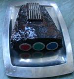
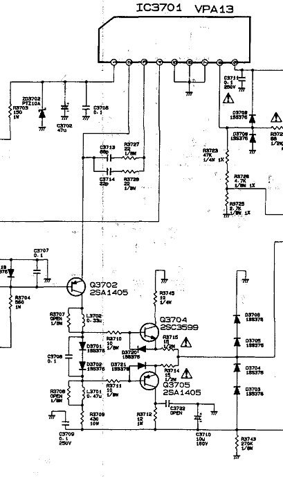
Not Electrohome is the only one who did nice yob with the CRT amplifiers though. In the NEC 6/9PG xtra there is a hybrid circuit where the Cathode side is driven with a VPA13 and the G1 side is driven with a discrete amplifier circuit through the VPA's emitter leads. (I think the Toshiba P7300 uses this technique too). And in fact the PG xtra fares quite well with bandwidth.
| Description: |
| PG xtra CRT driver circuit |
|
| Filesize: |
55.67 KB |
| Viewed: |
4056 Time(s) |
|
_________________
projectors in the past : NEC 6-9PG xtra, Electrohome Marquee 6-7500, NEC XG 1351 LC ( with super modified Electrohome VNB neckboard !!!)
current: VDC Marquee 9500LC
The MOD: VNB-DB, VIM-DB
|
|
| Back to top |
|
|
the dude
Joined: 11 Sep 2013
Posts: 179
|
| Posted: Wed Feb 17, 2016 7:07 pm Post subject: |
|
|
Thanks for explanations gjaky, thats quite interesting. I never thought of driving a probe as a load instead of the tube, but for sure the capacitance is quite in the right range. My probes can withstand 50V at 100 Mhz, so this would be quite useable.
The sony G70 uses a sanyo video pack for both cathode and G1, so i thougt that may be a good idea. But the G70 neckboards are known to run quite hot for sure. I once saw a machine with custom made water cooling. Not many parts really needed this, most would be happy with the slow fans that were still installed for basic cooling. The neckboards were one of the few parts that needed a water cooler!
Adapting the Electrohome neckboard would require some work, at least copying of the IK sens and sample/hold and the G2 regulator and a power supply but maybe it is worth the effort.
@Redfox: The advantage of the Tek scope isn't only the bandwidth, 300 Mhz is nice but thats not the point. It is analog, so the deflection speed affects the brightness and areas that are hit by the beam more than once will apear brighter also. So if for instance the area of the multiburst lines are uniform in brightness you know there is no ringing in the signal. It is easy to discover overlapping signals this way. Be sure to get a true analog scope. There are scopes with CRTs that are early DSOs, in this case the CRT is only a monitor.
If you are going to buy one of these late high BW Tek be aware of that horizontal deflection chip they use. It is custom made and inreplaceable, it serves several special functions like generation of readout cursors also. Unfortunally on some the internal chip bonding wires can lift up from the die, and if this happens the scope is garbage. You need some cooling for this, since heat up and cool down cyles are suspected to cause this due to termal stress. I made a heatsink for it so it runs quite cold.
And for the fury: I didn't test it at 75 Ohm, maybe i should get a T adapter and solder a resistor on it. Only this would give accurate results.
|
|
| Back to top |
|
|
gjaky
Joined: 05 Jun 2010
Posts: 2802
Location: Budapest, Hungary
|
| Posted: Wed Feb 17, 2016 7:27 pm Post subject: |
|
|
| the dude wrote: | Thanks for explanations gjaky, thats quite interesting. I never thought of driving a probe as a load instead of the tube, but for sure the capacitance is quite in the right range. My probes can withstand 50V at 100 Mhz, so this would be quite useable.
The sony G70 uses a sanyo video pack for both cathode and G1, so i thougt that may be a good idea. But the G70 neckboards are known to run quite hot for sure. I once saw a machine with custom made water cooling. Not many parts really needed this, most would be happy with the slow fans that were still installed for basic cooling. The neckboards were one of the few parts that needed a water cooler!
Adapting the Electrohome neckboard would require some work, at least copying of the IK sens and sample/hold and the G2 regulator and a power supply but maybe it is worth the effort.
|
The newer XG neckboards are using dual VPJ13S chips and that also runs very hot. G90 uses dual VPJ15S I guess that is also very hot, the good old Sony 1292 uses dual VPA15H (120V version of VPA15). Back in the day I could get a full set of sony 1292 neckboards, to upgrade the PG xtra's bandwidth, but then I've lacked quite a knowledge about these things, and finally turned out the bandwidth of the PG xtra is not even that bad after all.
Shortly after I got my XG and my quest had begun with the ridiculous bandwidth of my XG...
I just got an idea for the 909. the method used in the PG xtra could be used there too. With not tying the hybrids emitter peaking network to ground instead to a high freq PNP transistor etc. and after buffering connect it to G1.
This of course would increase the actual gain of the amplifier, therefore you could lower contrast, getting to a better bandwidth.
For starting there is a -40V line in the PS unit, that is an opportunity to save almost 40V on the cathode drive voltage...
_________________
projectors in the past : NEC 6-9PG xtra, Electrohome Marquee 6-7500, NEC XG 1351 LC ( with super modified Electrohome VNB neckboard !!!)
current: VDC Marquee 9500LC
The MOD: VNB-DB, VIM-DB
|
|
| Back to top |
|
|
the dude
Joined: 11 Sep 2013
Posts: 179
|
| Posted: Wed Feb 17, 2016 7:40 pm Post subject: |
|
|
|
Hmm, is there a special reason for using the cascode emitter to get the drive signal for g1? Use the lower cascode transistor as a driver for both stages and use less parts?
|
|
| Back to top |
|
|
gjaky
Joined: 05 Jun 2010
Posts: 2802
Location: Budapest, Hungary
|
| Posted: Wed Feb 17, 2016 8:11 pm Post subject: |
|
|
| the dude wrote: | | Hmm, is there a special reason for using the cascode emitter to get the drive signal for g1? Use the lower cascode transistor as a driver for both stages and use less parts? |
The input voltage is converted to current by the input transistor of the video pack (aka. the common emitter of the cascode - through the emitter resistor) , as you know almost the same current flows on the collector as on the emitter of that transistor. And since this collector current is actually which drives the cathode output, this very same current should drive the G1 too.
Of course you could build a full function negative side cascode too, but then you'd need a proper input signal to feed it, which will emerge biasing problems, to use level shifters and etc. Or the tail of the negative cascode should be fixed at some ugly positive level like 2-3V or so. The other way is more simple.
_________________
projectors in the past : NEC 6-9PG xtra, Electrohome Marquee 6-7500, NEC XG 1351 LC ( with super modified Electrohome VNB neckboard !!!)
current: VDC Marquee 9500LC
The MOD: VNB-DB, VIM-DB
|
|
| Back to top |
|
|
the dude
Joined: 11 Sep 2013
Posts: 179
|
| Posted: Wed Feb 17, 2016 8:50 pm Post subject: |
|
|
|
Ok, that makes sense!
|
|
| Back to top |
|
|
redfox001
Joined: 16 Mar 2009
Posts: 2257
Location: The Netherlands
|
| Posted: Thu Feb 18, 2016 11:10 am Post subject: |
|
|
| gjaky wrote: |
I just got an idea for the 909. the method used in the PG xtra could be used there too. With not tying the hybrids emitter peaking network to ground instead to a high freq PNP transistor etc. and after buffering connect it to G1.
This of course would increase the actual gain of the amplifier, therefore you could lower contrast, getting to a better bandwidth.
For starting there is a -40V line in the PS unit, that is an opportunity to save almost 40V on the cathode drive voltage... |
Barclay once said after trying lug tubes on marquee that possible with lug you need to drive cathode only. Because there is an extra grid somewhere on lug? He said lug bloomed very early with g1 and cathode drive.
_________________
701s->runco933->8500ultra->cinemax->9500mp->919 splitpack + cinemax
|
|
| Back to top |
|
|
|
|
|
|
|
You cannot post new topics in this forum
You cannot reply to topics in this forum
You cannot edit your posts in this forum
You cannot delete your posts in this forum
You cannot vote in polls in this forum
You cannot attach files in this forum
You can download files in this forum
|
Forum powered by phpBB © phpBB Group
|
|


