| Author |
Message |
CSX

Joined: 11 Feb 2015
Posts: 142
Location: Ohio
|
| Posted: Fri Mar 20, 2015 4:20 am Post subject: |
|
|
Curt, Possibly.
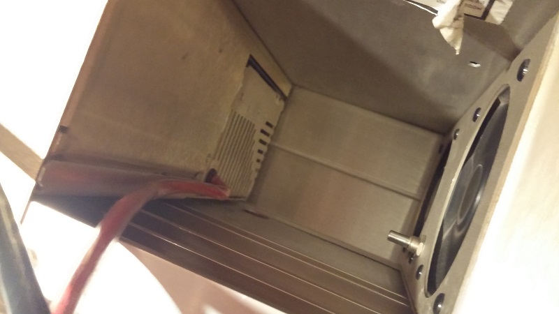
Here's a view from what I see.
The potentiometer in between the fans is the one I had to have brushed against.
When I made adjustments to it after taking a reading on P14, it was almost turned to the left completely... No silicone on it, but I had thoroughly inspected the supply before it's initial installation, and dialed it in.
I'm going to make sure it stays stable through the night, then will apply a locking agent to the stem.
| Description: |
|
| Filesize: |
74.51 KB |
| Viewed: |
5502 Time(s) |
|
|
|
| Back to top |
|
 |
Curt Palme
CRT Tech
Joined: 08 Mar 2006
Posts: 24396
Location: Langley, BC
TV/Projector: All of them!
|
| Posted: Fri Mar 20, 2015 2:00 pm Post subject: |
|
|
Yup, could be one of mine. It's possible someone took the silicone off at some point in time, as I always set the voltage, then apply the silicone, then measure the P14 again. Then again, I'm not the only one doing the mod like this.
Cheers!
|
|
| Back to top |
|
|
cmjohnson

Joined: 03 Apr 2006
Posts: 5180
Location: Buried under G90s
|
| Posted: Fri Mar 20, 2015 2:20 pm Post subject: |
|
|
Almost makes you want to build a heater voltage monitoring circuit that shuts down heater voltage or sounds an alarm if an overvoltage condition is detected, doesn't it?
It would be simple to make.
|
|
| Back to top |
|
|
CSX
Joined: 11 Feb 2015
Posts: 142
Location: Ohio
|
| Posted: Fri Mar 20, 2015 2:36 pm Post subject: |
|
|
| cmjohnson wrote: | Almost makes you want to build a heater voltage monitoring circuit that shuts down heater voltage or sounds an alarm if an overvoltage condition is detected, doesn't it?
It would be simple to make. |
Absolutely.
I'd like to implement the shutdown feature for the heaters, but for now, a monitor panel for the voltage tied in to P14 should do the trick. I'll be adding that until I can get an automatic shutdown happening.
|
|
| Back to top |
|
|
mac
Joined: 07 Nov 2012
Posts: 143
|
| Posted: Fri Mar 20, 2015 4:15 pm Post subject: |
|
|
|
I don't follow all the Marquee threads but why are you guys not just using a basic regulator circuit?
|
|
| Back to top |
|
|
Curt Palme
CRT Tech
Joined: 08 Mar 2006
Posts: 24396
Location: Langley, BC
TV/Projector: All of them!
|
| Posted: Fri Mar 20, 2015 5:41 pm Post subject: |
|
|
|
E'home did that on the later power supplies. I just didn't have the time to work one out, putting in a pot takes me 1/2 hour.
|
|
| Back to top |
|
|
Nashou66

Joined: 12 Jan 2007
Posts: 16171
Location: West Seneca NY
|
|
| Back to top |
|
|
redfox001

Joined: 16 Mar 2009
Posts: 2257
Location: The Netherlands
|
| Posted: Fri Mar 20, 2015 7:02 pm Post subject: |
|
|
Yes I measured the voltage to check it was 6,31 V and 4 V in standby. My lvps is a newer one. My blue tube has the filament glowing much more in stand by I think it has a lot of stand by hours. The new tubes hardly glow.
_________________
701s->runco933->8500ultra->cinemax->9500mp->919 splitpack + cinemax
|
|
| Back to top |
|
|
mac
Joined: 07 Nov 2012
Posts: 143
|
| Posted: Fri Mar 20, 2015 7:19 pm Post subject: |
|
|
Putting a resistor there or even a pot is not a good idea. Any fluctuations in the supply line would also fluctuate the filament voltage. A regulator and zener diode would hold the filament voltage constant regardless of supply voltage fluctuations.
|
|
| Back to top |
|
|
Nashou66
Joined: 12 Jan 2007
Posts: 16171
Location: West Seneca NY
|
|
| Back to top |
|
|
CSX
Joined: 11 Feb 2015
Posts: 142
Location: Ohio
|
| Posted: Sun Mar 22, 2015 3:23 am Post subject: |
|
|
On the newer style PSU, what is the expected P14 value?
I have one that came with the projector, but it wasn't in operational shape.
Got it running this morning, but I see 6.6x volts on P14 with it.
Is this within tolerance?
|
|
| Back to top |
|
|
barclay66

Joined: 27 Jun 2011
Posts: 1304
Location: Germany
TV/Projector: Marquee 9500 Ultra
|
| Posted: Wed Mar 25, 2015 8:10 am Post subject: |
|
|
Hi,
6.6 Volts at the P14 Connector looks OK when measured without load. There's a minimal voltage drop at the VNBs too.
The ideal voltage directly at the tube should be 6.35 Volts.
Less (e.g. 5.5 Volts) will make the picture look washed out with low contrast.
More (e.g. 7.5 Volts) will result in a punchy picture but it might cut off some Year of the tube's life expectance.
A small variation of 0.2 Volts shouldn't have any effect.
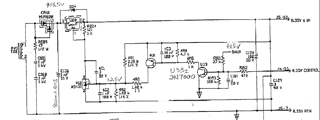
BTW: I'm preparing a DIY procedure for retrofitting older LVPS with the later model extra board (including building that board). That should be online within some days...
Regards,
barclay66
|
|
| Back to top |
|
|
CSX
Joined: 11 Feb 2015
Posts: 142
Location: Ohio
|
| Posted: Wed Mar 25, 2015 2:26 pm Post subject: |
|
|
Well. I guess I'll keep using my old PSU in place. Not sure what is up with the newer one, but it does some funny things that I won't trust until I go over it again.
I've already roasted one tube this month, don't need any more. 
I definitely appreciate the input, Barclay, and look forward to your DIY procedures.
|
|
| Back to top |
|
|
Nashou66
Joined: 12 Jan 2007
Posts: 16171
Location: West Seneca NY
|
|
| Back to top |
|
|
CSX
Joined: 11 Feb 2015
Posts: 142
Location: Ohio
|
| Posted: Wed Mar 25, 2015 5:58 pm Post subject: |
|
|
| Nashou66 wrote: | Barclay's the best !!!
 |
So I've come to learn
Now all I need is a replacement green tube 8)
|
|
| Back to top |
|
|
barclay66
Joined: 27 Jun 2011
Posts: 1304
Location: Germany
TV/Projector: Marquee 9500 Ultra
|
|
| Back to top |
|
|
CSX
Joined: 11 Feb 2015
Posts: 142
Location: Ohio
|
| Posted: Sat Mar 28, 2015 1:02 am Post subject: |
|
|
Amazing! Thanks! Keep up the excellent work. I'm placing an order asap 8)
|
|
| Back to top |
|
|
|
|