| Author |
Message |
Curt Palme
CRT Tech
Joined: 08 Mar 2006
Posts: 24396
Location: Langley, BC
TV/Projector: All of them!
|
| Posted: Tue Mar 10, 2015 10:53 pm Post subject: |
|
|
Right, but that's an open circuit he's measuring, as in a no load condition. I'll need to check the manual, but in the dozens of later model SMPS I've had through here, all read off slightly, none caused issues. I believe almost all of the secondary voltages come off one transformer. I could be wrong.
The other alternative is for me to sell him a tested working 3600 SMPS out of my stock.
|
|
| Back to top |
|
 |
macgyver655
Joined: 22 Aug 2007
Posts: 8508
|
| Posted: Tue Mar 10, 2015 11:06 pm Post subject: |
|
|
| Curt Palme wrote: | | Right, but that's an open circuit he's measuring, as in a no load condition. |
That is why I had him test "all" the other rails and they were also all off by a lot more then 20%. And clearly they should not be outputting higher then normal voltages when the projector is OFF.
| Curt Palme wrote: | | I believe almost all of the secondary voltages come off one transformer. |
No, 2 drive circuits.
| Curt Palme wrote: | | The other alternative is for me to sell him a tested working 3600 SMPS out of my stock. |
Well I guess you could start throwing all kinds of boards at until it works. 
At this point I don't really think it is the P/S either but if you cannot properly test voltages, how can you test for a short to gnd.?
|
|
| Back to top |
|
|
Luuk neele
Joined: 04 Mar 2015
Posts: 186
Location: Wijk bij duurstede, the Netherlands.
|
| Posted: Tue Mar 10, 2015 11:13 pm Post subject: |
|
|
Rectification : smoke came from the smps, the rgb board and somewhere at the amp in te top half.
I don't understand what I am doing wrong. Please teach me.
If I take the psu out and test all fuses in circuit for resistance, all should be 0. If I test the +40 and - 20 I get infinite.
In my opinion that's gotta mean there's something wrong in the psu.
|
|
| Back to top |
|
|
macgyver655
Joined: 22 Aug 2007
Posts: 8508
|
| Posted: Tue Mar 10, 2015 11:13 pm Post subject: |
|
|
| Curt Palme wrote: | Right, but that's an open circuit he's measuring, as in a no load condition. I'll need to check the manual, but in the dozens of later model SMPS I've had through here, all read off slightly, none caused issues. I believe almost all of the secondary voltages come off one transformer. I could be wrong.
The other alternative is for me to sell him a tested working 3600 SMPS out of my stock. |
So you think these voltages are acceptable?
| Quote: | -9 fuse has -18v
-40 has -87v
+25 is 30v
+20 is 19v
-25 has -46
+9 has 9 volt
+40 has 56 volt ------------ NO LIGHT
-20 has -42 volt ------------ NO LIGHT
+190 has 228v |
-87v on a -40v rail?
-42v on a -20v rail?
|
|
| Back to top |
|
|
macgyver655
Joined: 22 Aug 2007
Posts: 8508
|
| Posted: Tue Mar 10, 2015 11:22 pm Post subject: |
|
|
| Luuk neele wrote: | Rectification : smoke came from the smps, the rgb board and somewhere at the amp in te top half.
I don't understand what I am doing wrong. Please teach me.
If I take the psu out and test all fuses in circuit for resistance, all should be 0. If I test the +40 and - 20 I get infinite.
In my opinion that's gotta mean there's something wrong in the psu. |
No, that does not indicate the P/S is bad. When you have 2 blown fuses, that means there is a problem somewhere after the fuses. The P/S is before the fuses.
But you have odd voltages on the rails that should be good. But lets say that your meter is correct and those are the voltages that are being put out. Then your P/S would be driving to high of voltages.
So lets check something.
Pull that P/S back out. Locate Q1 and Q2. They are on those 2 heat sinks.
DMM on diode scale and test across various legs and compare one against the other and see if there are differences. And give me some of your readings.
|
|
| Back to top |
|
|
macgyver655
Joined: 22 Aug 2007
Posts: 8508
|
| Posted: Tue Mar 10, 2015 11:23 pm Post subject: |
|
|
|
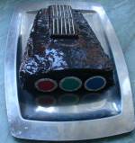
Snap a picture of your P/S also and post it if you can.
|
|
| Back to top |
|
|
Luuk neele
Joined: 04 Mar 2015
Posts: 186
Location: Wijk bij duurstede, the Netherlands.
|
| Posted: Tue Mar 10, 2015 11:51 pm Post subject: |
|
|
Here goes
| Description: |
|

Download |
| Filename: |
2015-03-11 00.50.49.jpg |
| Filesize: |
445.3 KB |
| Downloaded: |
265 Time(s) |
| Description: |
|
Download |
| Filename: |
2015-03-11 00.46.58.jpg |
| Filesize: |
343.95 KB |
| Downloaded: |
249 Time(s) |
|
|
| Back to top |
|
|
macgyver655
Joined: 22 Aug 2007
Posts: 8508
|
| Posted: Wed Mar 11, 2015 12:14 am Post subject: |
|
|
Those readings are fine.
In between those 2 large caps is a resistor (R9) and behind the right one (R10).
Give me the resistance reading on those 2. You have to lift 1 leg on each to properly test so fire up that soldering iron.
|
|
| Back to top |
|
|
macgyver655
Joined: 22 Aug 2007
Posts: 8508
|
| Posted: Wed Mar 11, 2015 12:16 am Post subject: |
|
|
|
OH, BE CAREFUL ON THOSE 2 LARGE CAPS! They are probably holding a charge. Try to discharge them before doing anything. Hold a resistor across each one to discharge.
|
|
| Back to top |
|
|
Luuk neele
Joined: 04 Mar 2015
Posts: 186
Location: Wijk bij duurstede, the Netherlands.
|
| Posted: Wed Mar 11, 2015 12:17 am Post subject: |
|
|
I'll do that first thing tomorrow afternoon.  thanks so far. thanks so far.
I can also get a nec xg1351 this one supposedly works too.
I'm actually enjoying this.
|
|
| Back to top |
|
|
Nashou66

Joined: 12 Jan 2007
Posts: 16171
Location: West Seneca NY
|
|
| Back to top |
|
|
gjaky
Joined: 05 Jun 2010
Posts: 2802
Location: Budapest, Hungary
|
| Posted: Wed Mar 11, 2015 7:35 am Post subject: |
|
|
The ampro accepts multi input voltages, but you have to select the range. Is that set to 230V operation?
Otherwise the NEC XG1351 is a fine machine too, but check for the tube condition, if the tubes have burnt, it is only good for parts machine, XG tubes are very hard to find (thus expensive too).
_________________
projectors in the past : NEC 6-9PG xtra, Electrohome Marquee 6-7500, NEC XG 1351 LC ( with super modified Electrohome VNB neckboard !!!)
current: VDC Marquee 9500LC
The MOD: VNB-DB, VIM-DB
|
|
| Back to top |
|
|
Luuk neele
Joined: 04 Mar 2015
Posts: 186
Location: Wijk bij duurstede, the Netherlands.
|
| Posted: Wed Mar 11, 2015 7:38 am Post subject: |
|
|
There's 220v coming from my wall outlet, so if it was set to 110v it wouldn't just blow up every fuse.
So yes, it's set to 220v
|
|
| Back to top |
|
|
Luuk neele
Joined: 04 Mar 2015
Posts: 186
Location: Wijk bij duurstede, the Netherlands.
|
| Posted: Wed Mar 11, 2015 7:33 pm Post subject: |
|
|
| macgyver655 wrote: | Those readings are fine.
In between those 2 large caps is a resistor (R9) and behind the right one (R10).
Give me the resistance reading on those 2. You have to lift 1 leg on each to properly test so fire up that soldering iron. |
R10 give me a reading of 77.7 in the 200k ohm mark
R9 gives me a reading of 1 (or no reading)
yes, legs are up.
|
|
| Back to top |
|
|
macgyver655
Joined: 22 Aug 2007
Posts: 8508
|
| Posted: Wed Mar 11, 2015 7:50 pm Post subject: |
|
|
Looks like R9 has failed. They should both be 75k ohm, 1watt. I recommend replacing both of them with 75kohm, 2 watt.
But before you go ordering parts, now you should check for short to ground so if you need more parts you can order them all at the same time.
Put all the boards and power supply back in but leave the 2 fuses, -20v and +40v out. Set DMM to diode scale. 1 probe on chassis ground and test the fuse holder end that is closest to the metal case. Test both the -20v and +40v and give me those 2 readings.
|
|
| Back to top |
|
|
Luuk neele
Joined: 04 Mar 2015
Posts: 186
Location: Wijk bij duurstede, the Netherlands.
|
| Posted: Wed Mar 11, 2015 7:52 pm Post subject: |
|
|
|
question: do i reconnect the resistors back into the board?
|
|
| Back to top |
|
|
macgyver655
Joined: 22 Aug 2007
Posts: 8508
|
| Posted: Wed Mar 11, 2015 7:52 pm Post subject: |
|
|
|
No
|
|
| Back to top |
|
|
Luuk neele
Joined: 04 Mar 2015
Posts: 186
Location: Wijk bij duurstede, the Netherlands.
|
| Posted: Wed Mar 11, 2015 8:40 pm Post subject: |
|
|
with just AC connected (no power)
+40 line reads .571
-20 line reads 0
with power on (before it turns off automatically)
+40 line reads .586
-20 line reads 0.09
|
|
| Back to top |
|
|
macgyver655
Joined: 22 Aug 2007
Posts: 8508
|
| Posted: Wed Mar 11, 2015 9:33 pm Post subject: |
|
|
|
Please do not turn the power on any more until you are told. Remove that power cord and give it to a responsible person.
|
|
| Back to top |
|
|
Nashou66
Joined: 12 Jan 2007
Posts: 16171
Location: West Seneca NY
|
|
| Back to top |
|
|
|
|