| Author |
Message |
jgrice53
Joined: 10 Dec 2014
Posts: 165
Location: marion, sc 29571
|
| Posted: Mon Dec 15, 2014 2:31 pm Post subject: |
|
|
i am going to try to get as many as i can to upload in this post
| Description: |
|
| Filesize: |
397.07 KB |
| Viewed: |
7811 Time(s) |
|
| Description: |
|
| Filesize: |
330.36 KB |
| Viewed: |
7811 Time(s) |
|
| Description: |
|
| Filesize: |
96.55 KB |
| Viewed: |
7811 Time(s) |
|
|
|
| Back to top |
|
 |
macgyver655
Joined: 22 Aug 2007
Posts: 8508
|
| Posted: Mon Dec 15, 2014 3:44 pm Post subject: |
|
|
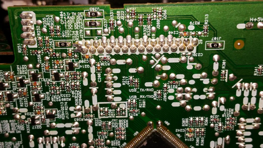
In the 1st photo you will see a yellow circle. In there is R264. The second photo is not clear enough so somewhere in that yellow circle is R295. I need you to set your DMM on DC voltage, should be able to ground your neg probe to chassis and then test both sides of both resistors with pos probe and give me the readings.


|
|
| Back to top |
|
|
jgrice53
Joined: 10 Dec 2014
Posts: 165
Location: marion, sc 29571
|
| Posted: Mon Dec 15, 2014 4:52 pm Post subject: |
|
|
|
0v on both sides of both resistors. chassis ground, plugged in but not on.
|
|
| Back to top |
|
|
macgyver655
Joined: 22 Aug 2007
Posts: 8508
|
| Posted: Mon Dec 15, 2014 5:00 pm Post subject: |
|
|
|
Try to turn on and see if voltage comes on.
|
|
| Back to top |
|
|
jgrice53
Joined: 10 Dec 2014
Posts: 165
Location: marion, sc 29571
|
| Posted: Mon Dec 15, 2014 5:16 pm Post subject: |
|
|
|
correction...3.2v on both sides of both resistor. my ground lead had fallen off when i got the 0v.
|
|
| Back to top |
|
|
macgyver655
Joined: 22 Aug 2007
Posts: 8508
|
| Posted: Mon Dec 15, 2014 5:22 pm Post subject: |
|
|
|
See if you can find R263 and test both sides of it.
|
|
| Back to top |
|
|
jgrice53
Joined: 10 Dec 2014
Posts: 165
Location: marion, sc 29571
|
| Posted: Mon Dec 15, 2014 6:12 pm Post subject: |
|
|
|
okay finally found it. 3.2v both sides
|
|
| Back to top |
|
|
macgyver655
Joined: 22 Aug 2007
Posts: 8508
|
| Posted: Mon Dec 15, 2014 6:38 pm Post subject: |
|
|
Lets see if it will allow a master reset.
While receiver is in standby, press and hold the "band" then also press the "standby/on" holding them for at least 3 seconds and see if the display reads "reset".
If it does then release those buttons and then press "auto surround/stream direct". It should now read "OK?" on the display. Then release that button and then press "ALC/standard surr" and the display should read "OK".
|
|
| Back to top |
|
|
jgrice53
Joined: 10 Dec 2014
Posts: 165
Location: marion, sc 29571
|
| Posted: Mon Dec 15, 2014 6:52 pm Post subject: |
|
|
|
okay mac. i followed your procedure and now when i turn it on it displays vol min for 3sec and then shuts off
|
|
| Back to top |
|
|
jgrice53
Joined: 10 Dec 2014
Posts: 165
Location: marion, sc 29571
|
| Posted: Mon Dec 15, 2014 6:53 pm Post subject: |
|
|
|
it is no longer giving the overheat error but it still will not stay on
|
|
| Back to top |
|
|
macgyver655
Joined: 22 Aug 2007
Posts: 8508
|
| Posted: Mon Dec 15, 2014 7:33 pm Post subject: |
|
|
|
Ok, 1 more resistor. R249. test voltage both sides.
|
|
| Back to top |
|
|
jgrice53
Joined: 10 Dec 2014
Posts: 165
Location: marion, sc 29571
|
| Posted: Mon Dec 15, 2014 7:46 pm Post subject: |
|
|
|
I am having trouble locating r249
|
|
| Back to top |
|
|
macgyver655
Joined: 22 Aug 2007
Posts: 8508
|
| Posted: Mon Dec 15, 2014 7:59 pm Post subject: |
|
|
|
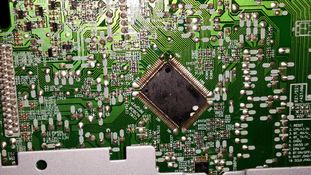
Well I think it is on the back side of the board. So you will have to test a pin right on the CPU ic. Pin number 19. Make sure you count and dont trust the numbers inked on the board.
|
|
| Back to top |
|
|
jgrice53
Joined: 10 Dec 2014
Posts: 165
Location: marion, sc 29571
|
| Posted: Mon Dec 15, 2014 8:16 pm Post subject: |
|
|
|
Which one is pin#1? the pin next to the white dot close to the ic203 label?
|
|
| Back to top |
|
|
macgyver655
Joined: 22 Aug 2007
Posts: 8508
|
| Posted: Mon Dec 15, 2014 8:33 pm Post subject: |
|
|

|
|
| Back to top |
|
|
jgrice53
Joined: 10 Dec 2014
Posts: 165
Location: marion, sc 29571
|
| Posted: Mon Dec 15, 2014 8:46 pm Post subject: |
|
|
|
right, that is what i came up with too. 0v on pin 19 and every pin on the ic except the pin at the opposite corner with the trace that goes under the r212 label. 181 or 182 i think. it has 3.2v
|
|
| Back to top |
|
|
macgyver655
Joined: 22 Aug 2007
Posts: 8508
|
| Posted: Mon Dec 15, 2014 9:17 pm Post subject: |
|
|
Test for voltage at pin 12 at yellow line. Verify the pin count.

|
|
| Back to top |
|
|
jgrice53
Joined: 10 Dec 2014
Posts: 165
Location: marion, sc 29571
|
| Posted: Mon Dec 15, 2014 9:21 pm Post subject: |
|
|
|
0v on pin 12
|
|
| Back to top |
|
|
jgrice53
Joined: 10 Dec 2014
Posts: 165
Location: marion, sc 29571
|
| Posted: Mon Dec 15, 2014 9:24 pm Post subject: |
|
|
|
i know you didn't ask but just to let you know, there is 0v on pin11 and 3.2v on pin10
|
|
| Back to top |
|
|
macgyver655
Joined: 22 Aug 2007
Posts: 8508
|
| Posted: Mon Dec 15, 2014 10:41 pm Post subject: |
|
|
|
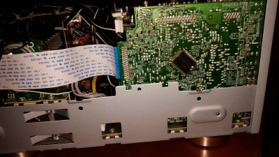
Looks like the next test points are down near the bottom and it doesn't look like you can reach them with the metal chassis there. So I guess you will have to remove the board and test them that way. DMM on diode and test Q203. Then DMM on resistance and test R248 and R249.
|
|
| Back to top |
|
|
|
|