|
As this forum is rarely used anymore, we've locked it. Feel free to browse and read. Questions? Please reach out to us directly. Cheers! |

|
 |
|
|
| Author |
Message |
szp72
Joined: 18 Nov 2008
Posts: 25
|
| Posted: Sat Nov 08, 2014 7:49 pm Post subject: HDMI splicing how-to |
|
|
I recently had to "upgrade" my component cable connections with HDMI cables; unfortunately, there was no way to slip the HDMI connector through the corrugated conduits running in my walls.
I looked around a little and found these HDMI connectors to solder:
http://www.toby.co.uk/content/catalogue/products.aspx?series=51S-019P-30N6
I ordered a few, but as soon I received them I understood that, unless I took a degree as a brain surgeon, there was no way that I could solder 19 wires in little more than 1 cm, at the same time keeping solderings "flat" so that they do not touch the metal shielding (you have about 2 mm between the little board and the metal shielding can, once closed).
I have no doubt there will be someone skilled enough to use them, but that's surely not me.
Another option was using 2 CAT6 ethernet cables, with an appropriate converter.
I read somewhere that HDMI cables can reach a bandwidth of 10.2 Gb, so I was a little skeptical that the signal transformed by these converters is not compressed in some way (and, moreover, the converters are not exactly cheap).
So I thought that maybe splicing the cable was, after all, a good solution.
There isn't a lot of literature around, and many comments firmly discourage the practice.
I don't know if I have been lucky, but since everything went smooth I'd like to share my experience.
I bought a 10 m, high-quality HDMI cable, already terminated; I cut the cable 40 cm after the connector and passed the cable in the conduit. Of course, you should keep the connector on the side that is more difficult to reach, and do the solderings on the more comfortable side.
I also suggest you do not have kids running around when you're doing the work 
Consider that it will take a few hours to get things properly done; maybe there will be some Superman that does this thing in 45 minutes: I prefer to take my time and do the things right the first time!
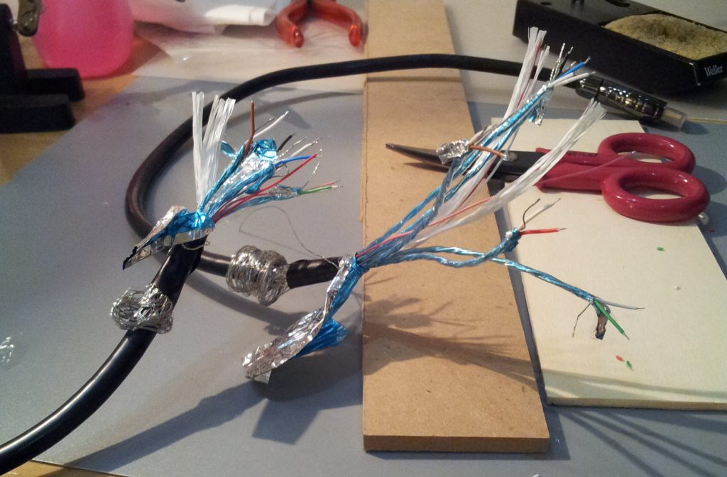
A HDMI cable is a very complicated little beast: there are 5 twisted pairs of wires, each having an additional exposed wire in-between; they are folded in aluminium foil, which is in turn wrapped in a transparent jacket. There are 4 additional insulated wires and dielectric material in the center: the twisted pairs and the cables are arranged around this soft, cotton-like core.
Another foil of aluminium wraps them all; over it, there is a metal mesh and a single exposed wire running for the length of the whole cable; finally, there is the plastic jacket of the cable.
The foil has two sides: one conductive (silver) and the other covered with insulating material (blue in the pictures). The twisted pairs have the blue side on the outside, while the foil which wraps all the cables has the blue side on the inside.
The first thing to do is is exposing the wires for soldering. Carefully remove the external jacket of the cable, leaving 8 cm on each side: you need this length to work comfortably.
Slide down the mesh, then the foil. Unwrap every twisted pair and separate the three wires.
Carefully expose 1.5 mm of the core for each wire; I suggest to use a tool for this operation, since it is essential to keep the exact length of every conductor.
In picture 1 you see the cable cut and ready to be soldered.
Arrange the cables so that you solder them in order, for example clock-wise; if you solder them at random you might have troubles in soldering wires between already soldered ones.
Since I used Wonder Solder, which has a low melting temperature, I avoided using shrinking tubes (heating the tube would desolder my wires); I just used electrical vinyl tape cut in small chunks to insulate each wire.
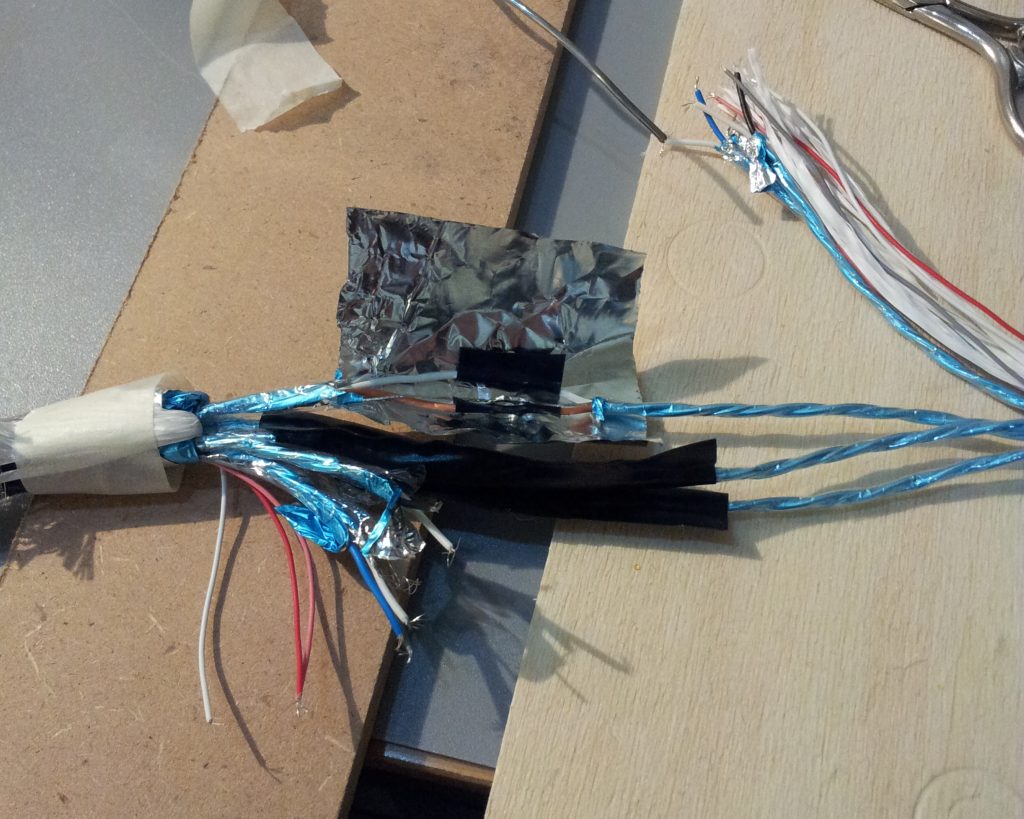
I wrapped every twisted pair in aluminium foil (the one used for cooking), and wrapped the foil in electrical tape because it is conductive and all the cables will be in contact at the end.
In picture 2 you can see two twisted pairs completed and a third which is being wrapped in aluminium foil.
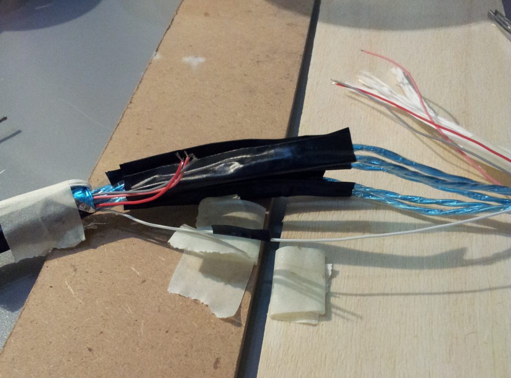
Next, solder the 4 single wires and insulate them (picture 3).
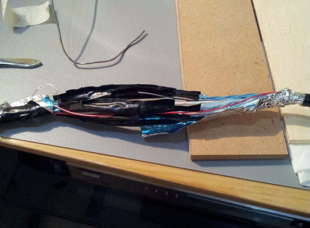
Slide up the existing aluminium foil (picture 4), then wrap the cable with additional foil; slide up the mesh and solder the single, external exposed wire (you will need to add a few mm of wire, since your cable is now a little "fat" where you spliced it).
Finish the cable with vinyl tape.
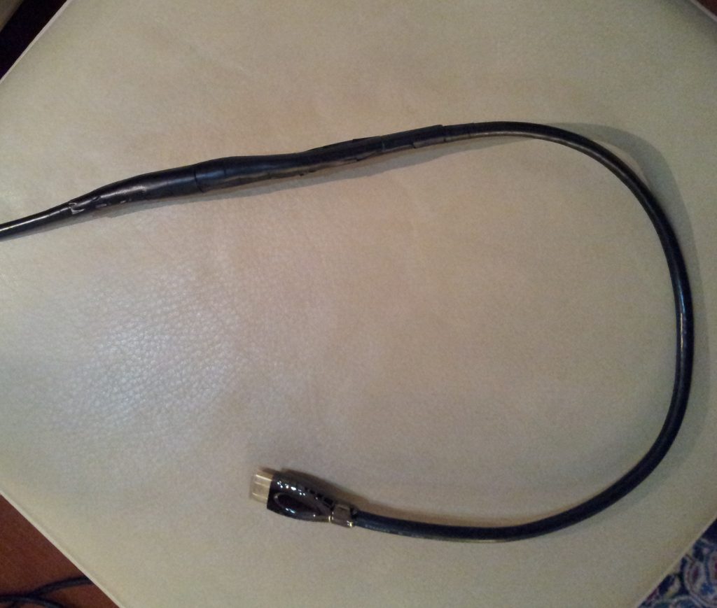
You can see the result in picture 5: not too bad!
It seems a snake having eaten too much, but this cable will be inside a cabinet and nobody will ever notice.
I tested the cable and compared the resulting image with an identical high-quality HDMI cable 7.5 m long.
I could not tell the difference, so I suppose everything is working as it should 
Cheers!
| Description: |
|
| Filesize: |
152.34 KB |
| Viewed: |
22077 Time(s) |
|
| Description: |
|
| Filesize: |
192.96 KB |
| Viewed: |
22077 Time(s) |
|
| Description: |
|
| Filesize: |
153.72 KB |
| Viewed: |
22077 Time(s) |
|
| Description: |
|
| Filesize: |
141.23 KB |
| Viewed: |
22077 Time(s) |
|
| Description: |
|
| Filesize: |
122.32 KB |
| Viewed: |
22077 Time(s) |
|
|
|
| Back to top |
|
 |
szp72
Joined: 18 Nov 2008
Posts: 25
|
| Posted: Sun Nov 09, 2014 7:32 am Post subject: |
|
|
A couple of things I forgot to mention..
Both ends of the cable are hard to be kept in position while soldering; my solution was using two tablets of wood, to which I sticked the cable ends using paper tape. In this way you can easily adjust the relative position of the wire ends.
It is important, indeed, that wire ends are in touch one with the other: even though Wonder Solder is good, its conductive power is lower than that of the wire being soldered, so its main function is keeping the touching wires in position.
Moreover, using a tool for exposing all the wires the same amount is recommended, because in this way you have a visible hint for overlapping before soldering; bare wires are the only exception - in that case you will need a good eye.
|
|
| Back to top |
|
|
paw

Joined: 08 Mar 2006
Posts: 1176
Location: Arvada, CO
|
|
| Back to top |
|
|
szp72
Joined: 18 Nov 2008
Posts: 25
|
| Posted: Tue Nov 11, 2014 8:28 am Post subject: |
|
|
@paw:
That's an interesting solution that I have missed, but I'm afraid that I would have had a hard time to pass these flying connectors: they seem longer and almost as large as the hdmi connector. My conduit was too small even for the beginning of the HDMI connector (the metal part). Neverthless, this could be a good solution for other people, if you want to spare the soldering time.
|
|
| Back to top |
|
|
CIR Engineering

Joined: 25 Aug 2008
Posts: 4269
Location: Chicago USA & Berlin Germany
|
| Posted: Wed Nov 12, 2014 4:47 pm Post subject: |
|
|
Nice work! I've never thought about trying it this way. I have used HDMI terminators like you described, but yes they are difficult.
As you knew, all the data lines MUST stay exactly the same length. Any deviation in length will cause data from differing length cables to arrive at the HDMI decoder at different times. This will result in no picture.
craigr
_________________
JETI 1501-HiRes 2nm Spectroradiometer
JETI 1211 Spectroradiometer
Photo Research PR-650 Spectroradiometer
Klein K10-A Colorimeter
Murideo Fresco SIX-G HDMI 2.x Multimedia Generator
Murideo Fresco SIX-A HDMI 2.x Analyzer
Light Illusion ColourSpace XPT Color Calibration Software
Light Illusion LightSpace XPT Pro Version 10.x Color Calibration Software
OMARDRIS JVC Software Patch to use K10-A and Jeti with JVC OEM AutoCal Software!
Sencore CR7000 CRT Tube Analyzer / Rejuvenater
Authorized Dealer for Lumagen & just about everything worth buying 
www.CIR-Engineering.com - craigr@cir-engineering.com
Phone: 865-405-6892
|
|
| Back to top |
|
|
szp72
Joined: 18 Nov 2008
Posts: 25
|
| Posted: Wed Nov 12, 2014 5:10 pm Post subject: |
|
|
Yes, I knew that, but I was confident that a certain tolerance was actually allowed!
I think there might be differences even if you are doing solderings on the small board of those connectors from Toby that I mentioned; for example, unless you are using a machine, the different wires might actually "touch" the tinned trace a little after or a little before; so you are changing length as well, because the signal is travelling a different distance on the connector.
Also, unless you desolder the wires from the old connector and then solder them on the new one, when you are cutting the cable you might get uneven wire lengths, for example because of a little uneven traction on the wires inside the cable that was applied when soldering the original connector.
When cutting and splicing the cable you end up with the original length, minus your precision in soldering the wires together, that I believe is more or less the one I could achieve if I could solder a Toby connector.
I could be completely wrong, of course; mine was a proof of concept, an attempt that I tried before going with more expensive solutions. Luckily it worked out! 
|
|
| Back to top |
|
|
CIR Engineering
Joined: 25 Aug 2008
Posts: 4269
Location: Chicago USA & Berlin Germany
|
| Posted: Wed Nov 12, 2014 6:39 pm Post subject: |
|
|
It's been a while since I looked at the speck, but I am pretty sure that I recall an HDMI cable should have all wires within 2mm of one another in length. Any more and your cable is outside spec.
When PCB's are built that use HDMI, you will notice some weird tracing if you look at the runs on the boards. Traces will go back and forth and make longer runs just to keep the length of the traces on the boards all the same length.
Any deviation here is critical to keep to a minimum.
I think your idea of stripping the wires exactly the same amount is a great idea. This is an easy way to keep all their lengths almost the same. If I ever do this, I will probably also use silver solder. Harder to work with, but better conductivity.
craigr
_________________
JETI 1501-HiRes 2nm Spectroradiometer
JETI 1211 Spectroradiometer
Photo Research PR-650 Spectroradiometer
Klein K10-A Colorimeter
Murideo Fresco SIX-G HDMI 2.x Multimedia Generator
Murideo Fresco SIX-A HDMI 2.x Analyzer
Light Illusion ColourSpace XPT Color Calibration Software
Light Illusion LightSpace XPT Pro Version 10.x Color Calibration Software
OMARDRIS JVC Software Patch to use K10-A and Jeti with JVC OEM AutoCal Software!
Sencore CR7000 CRT Tube Analyzer / Rejuvenater
Authorized Dealer for Lumagen & just about everything worth buying
www.CIR-Engineering.com - craigr@cir-engineering.com
Phone: 865-405-6892
|
|
| Back to top |
|
|
paw
Joined: 08 Mar 2006
Posts: 1176
Location: Arvada, CO
|
| Posted: Thu Nov 13, 2014 1:49 am Post subject: |
|
|
| szp72 wrote: | @paw:
That's an interesting solution that I have missed, but I'm afraid that I would have had a hard time to pass these flying connectors: they seem longer and almost as large as the hdmi connector. My conduit was too small even for the beginning of the HDMI connector (the metal part). Neverthless, this could be a good solution for other people, if you want to spare the soldering time.
|
I guess I missed giving you the 2nd half.
http://www.rapidrun.com/product_list.asp?cat_id=4135
This is the cable and narrower connector that you would pull through the conduit and the connect to the flying leads
_________________
Aubrey
|
|
| Back to top |
|
|
szp72
Joined: 18 Nov 2008
Posts: 25
|
| Posted: Thu Nov 13, 2014 9:17 am Post subject: |
|
|
Yeah, these are more reasonable; I probably could have used them. I'll keep them in mind in case I stumble again upon a similar situation. Thanks!
[quote="paw"]
|
|
| Back to top |
|
|
|
|
|
|
|
You cannot post new topics in this forum
You cannot reply to topics in this forum
You cannot edit your posts in this forum
You cannot delete your posts in this forum
You cannot vote in polls in this forum
You cannot attach files in this forum
You can download files in this forum
|
Forum powered by phpBB © phpBB Group
|
|


