|
As this forum is rarely used anymore, we've locked it. Feel free to browse and read. Questions? Please reach out to us directly. Cheers! |

|
 |
|
|
| Author |
Message |
ptkctc

Joined: 01 Nov 2013
Posts: 44
|
| Posted: Fri Nov 01, 2013 8:24 pm Post subject: question using rca chipper check on ptk195m? |
|
|
Hello, I am new here. I just have a question regarding the RCA chipper check interface and setting up the green convergence grid on a ptk195m series chassis.
I had an issue where all the convergence and pincushion circuits are good, but the screen displayed a top and bottom pincushion effect. Not on the sides, very top and bottom only.
I isolated it to the little 8-pin eeprom on the digicon board, you can swap one that has the most severe bow to the screen onto a digicon board that displayed a good square pic, and it goes to the previous boards display. It isnt anything after the eeprom, preamps, etc. Just the eeprom itself. I have 3 separate boards, 2 have the same bow to different degrees and one is fine except the green grid has lost a geometry setting for one spot in the center. The exact issues follow the eeproms no matter the board you solder it onto.
Is adjusting/rebuulding the green grid possible with chipper check on this chassis? I know a later model requires this if the eeprom frags out, in fact I remember them having to measure and tape a thread grid physically to the sides of the screen to aid setting it up since there was no reference to go by starting with the green.
If there is no such adjustment and its just a factory defaults type deal, since these digicon boards are all original, would just getting new eeproms fix the problem, and what would I need to do to the new chip before i could use it? I figure chipper check is required to at least "initialize" it and load the factory convergence specs before it would even function. (I repeat, this issue is not the common ones like the digicon amps themselves, its psb, or the pincushion circuit failure, they are working fine; its isolated to the eeprom on the digicons, U19500)
TY in advance, and any help is appreciated greatly. I try to go the the thomson network site, and it seems defunct since technicolor sa became the main company. Id gladly pay for the training manual for these chassis, they are the only model I have worked on, and i enjoy it even with the simple sams schematic I found for a ptk195b chassis. If I could get the service training manual, I bank that I could fix any issue short of a deflection board fire on these. I dont have chipper check yet, i need it I know because I have already come to points in troubleshooting that required it and i managed without. I will get it asap, esp if it will let me rebuild my convergence grids back from scratch.
|
|
| Back to top |
|
 |
ptkctc
Joined: 01 Nov 2013
Posts: 44
|
| Posted: Mon Nov 04, 2013 5:51 am Post subject: |
|
|
Anybody?
I have tried to get this info at a few other forums, and it seems like I have missed the boat on talking about these particular chassis' by about 10 years lol.
I am gonna acquire a chipper checker kit anyways, the tuner on one of my sets needs a little tweaking, and I will at least get that much use out of it. I will then find out if it will let me work on the green convergence points manually, or if simply wiping and "re-initializing" the digicon eeproms I have will fix the bowing screen problem. I figure if it can't do anything to correct it via software with the current eeproms, new eeproms should do the trick as something has failed inside them and the data is becoming corrupted as its being written. BTW the eeproms part number is " 24wc16p", I have searched and it seems its used in a few other applications besides televisions.
|
|
| Back to top |
|
|
barclay66

Joined: 27 Jun 2011
Posts: 1304
Location: Germany
TV/Projector: Marquee 9500 Ultra
|
| Posted: Mon Nov 04, 2013 9:35 am Post subject: |
|
|
Hi,
I don't think that the EEPROM is the culprit. In this application, the EEPROM is used as non-volatile memory for the convergence settings. Even if it was faulty it should be possible to adjust the convergence. It just wouldn't be stored and therefore the settings would be lost when powering down the set.
Still I find it very interesting that the problem follows when swapping the EEPROMs. Maybe it's worth trying a new one. You might need to do a complete convergence realignment in the service menu after mounting a blank EEPROM though.
I found the schematic for Your set here: http://diagramas.diagramasde.com/televisores/PTK195M.pdf
The schematic does mention the ChipperCheck hardware, but not in the context with convergence settings. Those should be doable with service menu routines only. Therefore I don't think that You need any additional equipment.
And I found a datasheet for the similar deflection processor STV2050. It explains quite well what the processor is using the EEPROM for.
BTW: If the service menu has a setting for N/S correction (North/South correction) or someting like top/bottom bow, I would try this first. Basic picture geometry should be aligned before touching convergence controls.
Regards,
barclay66
| Description: |
|

Download |
| Filename: |
STV2050A.pdf |
| Filesize: |
643.83 KB |
| Downloaded: |
6 Time(s) |
|
|
| Back to top |
|
|
ptkctc
Joined: 01 Nov 2013
Posts: 44
|
| Posted: Mon Nov 04, 2013 10:52 am Post subject: |
|
|
| barclay66 wrote: | Hi,
I don't think that the EEPROM is the culprit. In this application, the EEPROM is used as non-volatile memory for the convergence settings. Even if it was faulty it should be possible to adjust the convergence. It just wouldn't be stored and therefore the settings would be lost when powering down the set.
Still I find it very interesting that the problem follows when swapping the EEPROMs. Maybe it's worth trying a new one. You might need to do a complete convergence realignment in the service menu after mounting a blank EEPROM though.
I found the schematic for Your set here: http://diagramas.diagramasde.com/televisores/PTK195M.pdf
The schematic does mention the ChipperCheck hardware, but not in the context with convergence settings. Those should be doable with service menu routines only. Therefore I don't think that You need any additional equipment.
And I found a datasheet for the similar deflection processor STV2050. It explains quite well what the processor is using the EEPROM for.
Regards,
barclay66 |
Thank you barclay66, I must have got the model wrong, because the schematic shows the fist design psb which utilizes a STK-type integrated circuit chip instead of the discrete components of the second style which I have. I am sorry about that, my mistake 
My two chassis' are (1.) PTK195M4T and (2.) PTK195M4B. They are both from RCA "937" series ptvs, as in the same level of options like no dual tuner, no RGB component inputs, same guide plus, even same 1.22 software version. Just different screen sizes and lens/focus adjustments (I am always looking for a good '950-series mainboard lol). I have yet to actually come across the exact schematic for these chassis' online but the ones I can are close enough, except the psb and there are places that deal with the dynamic focus that are tied in with my digicon' that are different for those listed. I thank you for any help as to locating this document.
As to the eeproms I find it odd too that it follows them, I venture to say both the digicon boards I have that the fragged eeproms came from, were involved with some catastrophic event with the input voltages. Theres my 61" p61937, when I got the set both the digicon psb was dead and main deflection pincushion circuit was out due to a bad MUR460 diode. After repairing the issues, it has the same warped, bowed picture as the other set with the board I bought, just lessened. More on the bought board next...
Theres my p52937 and it had a great, very nice geometrical picture but I had the blue "drop down" in a spot, and in my frustration I bought the used board. Well, after aligning the convergence and adjusting the svc menu, it has the same bow as the 61" board, but extremely exaggerated. Its the same effect as if the pincushion circuit is out, except the sides are not affected; only the top and bottom. What I mean by this is the picture, when no pincushion correction is coming from the ctc195 mainboard pin amp circuit, the picture has a top bow where center of the arch is biased to the right; the bottom biases towards the left along with massive E/W pincushion. This is the same with the pincushion circuit functioning and the suspect eeproms effect, except its not as extreme and its only the top and bottom, the sides are perfectly straight.
I can swap either board into the 61" and its the same effect; I have swapped the 61" main board into the 52" lightbox to make sure it wasnt the pin amp I repaired causing its bow, and it will produce a nice square pic with whichever board that had that eeprom in it.
------I seriously almost lost my mind swapping components and parts around between boards and chassis' lol, its an extremely longwinded, repetitive-sounding story as you can see, and it took a couple of weeks to get to this point. I am no pro either, I just love these tvs and can't afford a new set of equal size at this time.
The most interesting is I managed to adjust the blue back to where it belonged on the square board but I had the green raise up in a single spot before getting done...... This issue follows this eeprom, along with its very square picture.
I will post some pics in a little bit to further show what is going on.
Its definately odd, but it may be where my p61937 chassis has had a bad malfunction for whatever reason in the past (I actually got it free for parts and simply fixed it), and I also put some things together in my head and figured out the used digicon board I bought likely came from a totaled set which suffered a really bad glycol leak (there were evidence of dirt/sticky stains on and around the rfi shield cover and in some tight spots on the board which I cleaned up) so It leads me to the conclusion that some event causes the eeprom to fail in some way that causes this effect.
Electrical surges may corrupt and damage something weird somehow with the eeproms. I didnt ever, EVER think to try swapping them around until I had almost given up.
Between the two boards for the 52" I swapped the two STV preamp chips, all the green vert and horiz transistors including resistors even if they tested good just in case and I NEVER saw a single change. I even tested and swapped most of the preamp surface mount circuit including the little fets around the main IC and the two STV chips and not a thing changed. Very dismaying.
I knew I would never manage to swap the main IC U19502 and have them in shape to be reinstalled with my skill level and would have to send them off if they were the problem, so I decided to try the u19500 as a very last resort before condemning U19502 as the culprit. Voila, I got instant gratification after swapping it. I was disappointed initially due to it not having the desired effect.
I was hoping to swap the "non corrup" eeprom as i thought from the used board, which didnt have the green convergence raised up but the bad bowing effect, onto the initial 52" board to hopefully have one working board which didn't have the now "unadjustable" green convergence error and bowing to the top and bottom, but am glad now to finally have isolated it to a single component.
There is something strange going on here in any case, I also note that these two sets I have are very sensitive to temperature convergence-wise; 8-10 degrees difference in room temp causes the convergence to shift slightly. Also the discoloration of the inside of the metal rfi box cover indicates the two STV preamp chips and the main digicon IC have run pretty hot on all these boards. Ill get the pics posted, I have quite a few as i have been working on them.
BTW there is no svc menu setting for N/S correction that I can access currently, just E/W. If there was it would be great because thats exactly what I need corrected. I am hoping thats one of the chipper checker only settings. This is my main concerns now, If chipper check can fix this issue by wiping and rewriting the chip, I may not even need new chips, just a "reinitalization" if you will due to corrupt data.
|
|
| Back to top |
|
|
ptkctc
Joined: 01 Nov 2013
Posts: 44
|
| Posted: Mon Nov 04, 2013 12:09 pm Post subject: pics |
|
|
square-display eeprom with initial blue issue but square pic:

square display eeprom after adjustment with green issue but still good square pic.......

Bought used board eeprom with extreme top and bottom issue:

Another:

and another:

For comparison, heres what the 61's looks like;
With no pincushion correction, its dead here:

Heres its original board in a chassis with functional pincushion circuit:

(some people say this is good; its alot more square in person w/the eeprom that has the green spot thats fubar'd than this, I still see a wavy looking pic when moving scenes slowly move across the screen and the bow to the top and bottom).
I hope this helps explain the dog that I have been chasing, w/o confusing you too much!
|
|
| Back to top |
|
|
barclay66
Joined: 27 Jun 2011
Posts: 1304
Location: Germany
TV/Projector: Marquee 9500 Ultra
|
| Posted: Mon Nov 04, 2013 12:14 pm Post subject: |
|
|
| ptkctc wrote: | | BTW there is no svc menu setting for N/S correction that I can access currently, just E/W. If there was it would be great because thats exactly what I need corrected. I am hoping thats one of the chipper checker only settings. This is my main concerns now, If chipper check can fix this issue by wiping and rewriting the chip, I may not even need new chips, just a "reinitalization" if you will due to corrupt data. |
Maybe that's the case (at leas I hope that for You). I would try a new (blank) EEPROM anyway. Those ones should be fairly cheap and it would be interesting to see how the set behaves with it...
Regards,
barclay66
|
|
| Back to top |
|
|
ptkctc
Joined: 01 Nov 2013
Posts: 44
|
| Posted: Mon Nov 04, 2013 12:22 pm Post subject: |
|
|
| barclay66 wrote: | | ptkctc wrote: | | BTW there is no svc menu setting for N/S correction that I can access currently, just E/W. If there was it would be great because thats exactly what I need corrected. I am hoping thats one of the chipper checker only settings. This is my main concerns now, If chipper check can fix this issue by wiping and rewriting the chip, I may not even need new chips, just a "reinitalization" if you will due to corrupt data. |
Maybe that's the case (at leas I hope that for You). I would try a new (blank) EEPROM anyway. Those ones should be fairly cheap and it would be interesting to see how the set behaves with it...
Regards,
barclay66 |
'
I found some on ebay that are either NOS or used, depending on the inventory for cheap. I also searched and found an independent seller who has them for roughly 1/3 the price of the already cheap ebay price, but I am leery of those because they are not the same manufacturer as the originals. The ebay ones appear and spec to be exact replacements.
Ill go ahead and pick up a couple when I get a chipper checker set, and Ill update this and hopefully have solved this weird, grossly misdiagnosed issue I have been blessed with, LOL! (EVERYBODY says digicon board, its psb or the pinamp but I have proven beyond a shadow of a doubt it follows the eeproms, not the digicon boards themselves).
Thank you again, barclay66.
|
|
| Back to top |
|
|
ptkctc
Joined: 01 Nov 2013
Posts: 44
|
| Posted: Mon Nov 04, 2013 1:35 pm Post subject: |
|
|
-I forgot to mention this tidbit, if I could do a manual adjustment of the green convergence, that would fix all my eeproms.
If the memory is stored in the eeprom, and it includes the default green memory's individual settings (the advanced green settings, like if you could adjust the green just like the red and blue in advance convergence, the svc menu only has 8 green geometry settings and they are more global like the ctc195 mainboard in direct-view mode's pincushion adjustments , its not even close to the precision you can adjust the red and blue when piggybacked with the ptv board), then maybe the green grids advanced geometry settings are "read only", used as a reference for the svc menu global adjustments and somehow corrupted during a power spike?
It makes sense to me and adds up as to why the issues follows the eeproms. If I could adjust the green, I know the red and blue could be perfectly aligned to it as theres quite a bit of adjustment room as you spread out spots and work your way around the grid. There has to be a "reference" memory for the individual green convergence, even if its just read-only. If it got corrupted somehow or scrambled it couldn't be adjusted back like the blue was in the first pic i posted. It looks like a transistor blew on the blue circuit but after realizing it was like the blue folded back into the screen in 3d, I adjusted all that back to normal except the green moved in the center before I got done with the blue.......
Like I stated, I am not a rich man by any means so Its been killing me waiting on having enough spare change after bills and food to purchase the chipper checker! Ill update this regardless of whenever I get it and some blank eeproms. If anybody had ever documented chasing this issue as well as I am doing here, It would have saved me about a week and a half of trial and error .
EDIT: I thought about something just now....
The svc menu setting stay with the mainboards, even with the digicon disconnected from its psb, the svc menu appears and the settings stay. The only difference is they have no effect wherever you set them, and the 3d green svc menu only grid does not appear either. Its like where the ptk195 is based on the ctc197 direct view mainboard, those svc menu settings are coming from the mainboard itself, not the digicon board. I assume the digicon just stores a default green convergence pattern in regards to the ptv functions and its supposed to be perfect so the red and blue will align with ease. In event that the green data gets scrambled somehow, you end up with my issue here.
Last edited by ptkctc on Tue Nov 05, 2013 7:37 am; edited 1 time in total
|
|
| Back to top |
|
|
ptkctc
Joined: 01 Nov 2013
Posts: 44
|
| Posted: Tue Nov 05, 2013 7:34 am Post subject: CTC195/197 training manual |
|
|
I finally found the training manual for these:
http://diagramas.diagramasde.com/televisores/CTC%20195%20-%20197%20TRAINING.pdf
I am gonna correct my previous post regarding "ptk195 being based on ctc195" and associated info, as I had it partially right but incorrectly stated that the direct view version of ptk195 was considered ctc195... a ptk195's mainboard is actually a ctc197 direct view mainboard, and when piggybacked with the ptv/digicon board, multple crt boards and associated projection gear that makes it a ptv, it is then considered a ctc195 mainboard (???! lol!).
The main reason I never found this very helpful 184 page manual before is that I was looking for a ptk195-specific manual when it turns out its all outlined in a section of the ctc195/97 training book.
I have the ITC222 training manual, and it heavily mentions the ctc195 in comparison to the ITC222's functionality to give examples of basic operation differences and service procedures.
I knew, judging by how far in-dept the ITC222 trainer went into, that I would really enjoy the ptk195 equivalent. I am glad I have it now to study, I will read it front to back several times before actually utilizing it on the bench lol!
I managed to do all I have listed just with help from nice people like here and all over the world online, my multimeter, a sams schematic thats not exactly for my model, and an ITC222 training manual. Earlier I fixed a blown ptk195 rev.2 psb by pulling and testing resistors. An open 390k resistor, u19701 was all that was wrong with this one. So I now have a good spare psb... I could have saved some cash if I knew all that I know now about these boxes two months ago lol!
|
|
| Back to top |
|
|
barclay66
Joined: 27 Jun 2011
Posts: 1304
Location: Germany
TV/Projector: Marquee 9500 Ultra
|
| Posted: Tue Nov 05, 2013 7:52 am Post subject: |
|
|
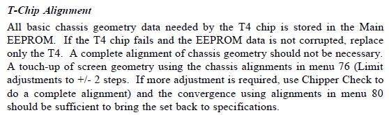
Page 150:
| Description: |
|
| Filesize: |
41.8 KB |
| Viewed: |
35 Time(s) |
|
|
|
| Back to top |
|
|
ptkctc
Joined: 01 Nov 2013
Posts: 44
|
| Posted: Tue Nov 05, 2013 7:59 am Post subject: |
|
|
| barclay66 wrote: | | Page 150: |
Awesome! I have my answer now, these chassis's must be unlike other brands approach to ptv, as i had guy on another forum tell me that "they are a different animal, with the separate digicon, separate psb for it, and etc. I didnt get it then, but he was referring to how the thomson ptk195 sets piggyback off a direct view tvs mainboard.
Thank you barclay66, I will consider this a solved issue for now. I will return once I can confirm through hands-on experience that this is indeed the fix.
|
|
| Back to top |
|
|
ptkctc
Joined: 01 Nov 2013
Posts: 44
|
| Posted: Sat Nov 16, 2013 1:27 am Post subject: |
|
|
Well, I finally got my chipper check 2 today.
I decided to go ahead and wait on new eeproms for the moment, just in case it was simple adjustments needed instead of replacement.
I got it to connect, and went to adjust the "25 point grid" with the green. I was able to perfect the geometry of the picture, no more bow to the bottom and top of the pic.
After going through the program just to check it out, I disconnected it and was gonna go on and open up the next rca set I have that needs the same procedure when I noticed the blue on the last set was off in a couple of spots on the convergence grid.
I went into advanced convergence, and I touched up the blue error, but before I got out of advance convergence, the entire screen jumped around and had a split second of "interference" (idk what else to call it, its like when you are in convergence and adjusting on any other set and your source signal gets bad enough to mess up the screen, even though you aren't actually viewing the signal), and after the screen returned to normal, I had an EXTREME bow of green at the top drop down, its not the same as the one i just got done correcting, its worse and irregular in comparison. The bottom was not disturbed.
It seems that both of my PTK195's are suffering from some kind of phenomenon that causes the green convergence data stored in the eeprom as ROM to get corrupted, causing the eeprom to skew the convergence everytime it happens.
It happened to me once with the blue, and it was so bad that most said the transistors on the digicon board were shot. After messing with the customer advance convergence, I was able to put the blue back exactly where it belonged. It was out BAD, it looked like the blue scan lines had bent back into the picture and folded back forwards into the other scanlines. This is the same thing that happens to the green when it goes out of adjustment with the exception that chipper check is required to adjust it back.
I suspect the dedicated I2C bus thats only for the digicon IC being compromised, but I have already pulled the smd components under the digicon shield and scrapped the glue out from under them. Even the gnat-sized FETS, and i have went over the very short circuit between the digicon IC and its dedicated eeprom and it all checks out.
Lets hope its just faulty eeproms, they have gotten hot at some point as evidenced by the discoloration on the bottom of the rfi shield cover. Its turned it yellow/brown above all the chips that are contained inside, eeprom, digicon IC, and both STV chips.
I will report back once I get new eeproms, Ill save and copy the best eeprom I have now to save some time rebuilding the convergence, and ill write the data to the new eeproms and see if they will hold settings better than they currently do.
A side note, the entire time I have been working on these PTK195's, when in the advance convergence menu there are certain oddities I have noticed. The convergence data will sometimes get corrupted as it saves the data, and it will be worse than you started once done. I ignored it initially and readjusted until it saved it properly. It was when the green decided to take off and readjust itself that I became concerned/disturbed/disappointed. I originally had code 16 on both sets (every single ptk195 I have ever looked at has this code set, from conductive glue pulling the I2C down to "zero logic"), but after removing the glue, no more occasional shut offs, and no more code 16. The glitching convergence was the same before removing the glue so Im not sure its related, but its something to think about.
|
|
| Back to top |
|
|
|
|
|
|
|
You cannot post new topics in this forum
You cannot reply to topics in this forum
You cannot edit your posts in this forum
You cannot delete your posts in this forum
You cannot vote in polls in this forum
You cannot attach files in this forum
You can download files in this forum
|
Forum powered by phpBB © phpBB Group
|
|


