|
As this forum is rarely used anymore, we've locked it. Feel free to browse and read. Questions? Please reach out to us directly. Cheers! |

|
 |
|
|
| Author |
Message |
mc86
Joined: 20 Sep 2008
Posts: 767
Location: pittsburgh, pa
TV/Projector: ECP 4500 (Vidikron box), ECP4500+, wanting 07MS/07MTS, evaluating pc soft-blend
|
| Posted: Sat Jun 08, 2013 1:01 am Post subject: Phosphor browning experiment |
|
|
On another thread SC wrote:
| ecrabb wrote: |
Really? Seems like the tubes on my machines were always quite warm. Since the tube and LC hardware was quite warm to the touch, I assumed the local heat on the phosphor and face of the tube was much higher. I wonder why the glycol is necessary at all if not to dissipate heat.
SC |
I was going to wait until I'd actually carried out some experiments along the lines of Crabb's musings before I posted this nutball scheme, but...here goes. Your help me do this study more intelligently and maybe such that it is of some utility and not me just futzing around. So I welcome suggestions and thoughts.
Motivation
The thread about using masks to balance-out/make uniform any uneven burn-in on a tube is one I think is awesome -- good concept, clear description, great results -- neat! People made suppositions about browning of the tube face as a function of IRE/drive, time on, etc. The aggregate experience clearly implied that the electron-density flux (absorbed and emitted as light while heating) accelerates the burn-in process and does so in a highly non-linear way. I'm not sure the mechanism can be identified per se, but some basic insights can be easily gathered -- especially wrt temperature, heat rates, and browning. The goal: to evaluate if enhanced tube face cooling via glycol flow and temperature control could helps preserve tube life. A flow system could also allow continuous filtering and easy replacement of the glycol.
To probe this, I am taking a 7"ES tube and am proposing two simple experiments.
Experiment 1
Remove the glass plate and the optical fluid (glycol). Display three distinct vertical zones of 100IRE, 60IRE, and 20IRE while monitoring the surface temperature with a thermographic camera over time until a steady-state is reached OR a significant temperature gradient is established and I'm scared uneven thermal expansion will implode a tube. It may be hard to calibrate the camera well, but it will show relative trends pretty well. I'll place two surface mount, low-thermal mass TCs on the tube face at the coldest and hottest expected zones. I will photograph the tube surface before/after and perhaps intermittently during the trial. Replicates are unlikely to be performed.
Experiment 2
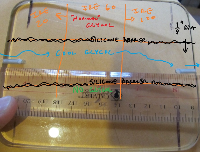
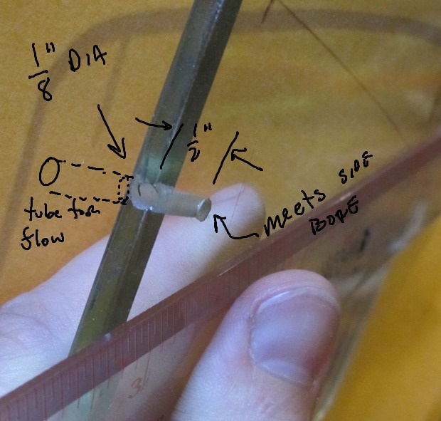
(see the picture and sketch below)
I have already used a diamond drill to drill a single 1/8" Dia hole into both edges of a tube glass plate. The holes penetrate about 1/2" in from each edge. Two additional holes were drilled orthogonal to the face, meeting the sides hole and thereby forming a letter "L" channel. See the picture below. I am bonding a thin-walled stainless steel tube to both holes to allow chilled glycol to be pumped through a section of the tube face. By putting two parallel, horizontal strips of silicone along the tube face, I will create three horizontal zones: One with no glycol on the bottom, one with chilled glycol, and one with standard glycol on the top of the tube. By using the same IRE pattern above, this will create 9 different zones on the tube face. I'll monitor the impact on tube burn-in periodically with a standard camera AND will place a surface mount thermocouple in each of the three zones. The cooled fluid will enter on the 20IRE end such that it will remain as constant in temp across the three zones as possible.
I need to estimate the power/area maximum for IRE 100 at a given drive setting somehow to get an order of magnitude feel for what might happen. That is, if a single tube gets ~60 watts at full 100%IRE, max drive, then 1/9 the area might be 6W/sector, with a sector being ~2 in^2 => 3W/in^2. That is a lot of energy...not sure how much is light and how much is heat and/or if the ratio of light:heat has a max at which more driving only heats the tube face. Anyone know the current pulled by the tubes and at what voltage during max drive and full white...?
In conjunction with all this -- IF the tests clearly show cooling the tube face reduces the rate of tube browning, I will create a model of the system in COMSOL that can allow for simulation of the heating AND of how flowing glycerol would cool the tube face in order to minimize stagnant zones/hotspots.
Thoughts?
Matt
| Description: |
| Modified glass plate with markings showing the zones that would be present during testing. |
|
| Filesize: |
148.92 KB |
| Viewed: |
7463 Time(s) |
|
| Description: |
| Hole I bored into the glass, forming an "L" shaped tube to allow flow of glycol. |
|
| Filesize: |
104.79 KB |
| Viewed: |
7463 Time(s) |
|
|
|
| Back to top |
|
 |
ecrabb
Forum Moderator

Joined: 13 Mar 2006
Posts: 15909
Location: Utah
TV/Projector: JVC RS40, Epson 5010
|
| Posted: Sat Jun 08, 2013 2:37 am Post subject: |
|
|
Do it!!! I would love to see the results!
SC
|
|
| Back to top |
|
|
Nashou66

Joined: 12 Jan 2007
Posts: 16171
Location: West Seneca NY
|
|
| Back to top |
|
|
CasetheCorvetteman

Joined: 09 Nov 2008
Posts: 6326
Location: Australia
|
| Posted: Sun Jun 09, 2013 1:29 am Post subject: |
|
|
|
Nashou, why is that? I thought they had a less dark C element in them?
|
|
| Back to top |
|
|
Nashou66
Joined: 12 Jan 2007
Posts: 16171
Location: West Seneca NY
|
|
| Back to top |
|
|
mc86
Joined: 20 Sep 2008
Posts: 767
Location: pittsburgh, pa
TV/Projector: ECP 4500 (Vidikron box), ECP4500+, wanting 07MS/07MTS, evaluating pc soft-blend
|
| Posted: Sun Jun 09, 2013 3:20 am Post subject: |
|
|
Wait Nashou...so the same set of tubes in two different machines wear at different rates? Cool, but how does this make sense? Presuming greyscale is correct on both AND the light output is the same, what can this mean?
1) The c-elements/lens (lightpath) filters more light in some cases than in others, so they are driven differently to get same light onscreen at correct greyscale. For the wear rate differences to be easily noticed, this must be pretty significant. Sounds like sign is wrong though, if in fact some G90 green c-elements are less dark.
2) There is something about the magnetics, perhaps -- maybe the beam is more focused than needed in one case than another, thereby requiring more drive to excite the same phosphor width as in a less focused beam in another case? By pouring more power into a local spot to excite neighboring areas ("microblooming"?), a localized heating might occur. I'm making this up, but I could be convinced of it. I could draw a picture if my words don't make sense. That is, if green is being made to do focus for 2000lines and only needs to do 1080, does this make the lines overdriven vs case in which focus is relaxed? I feel I should know this by now...
3) not sure I can makeup another idea at this hour...maybe cliffy is in a "creative place" right now and can chime in.
Matt, who is leaving on vacation for the next week (poconos) in the morning and will be mostly out of communication while away.
|
|
| Back to top |
|
|
CasetheCorvetteman
Joined: 09 Nov 2008
Posts: 6326
Location: Australia
|
| Posted: Sun Jun 09, 2013 4:26 am Post subject: |
|
|
I understand what youre saying mate yes 
Whether its a fact or not is not something i know 
|
|
| Back to top |
|
|
Nashou66
Joined: 12 Jan 2007
Posts: 16171
Location: West Seneca NY
|
| Posted: Sun Jun 09, 2013 4:35 am Post subject: |
|
|
Well I know the cutoff voltage for the marquee is lower than that of the G90, ampros and I think Barcos.
The marquee's is 170 and most CRT work optimally at 180 I do believe. This is why some say( I think Scott told me this) that the G90 and Ampros were sharper than the Marquee's. So I just hypothesized that since they send a sharper electron beam to the phosphor , that a more concentrated area of phosphor would get hotter and therefore wear faster. And the higher voltage might also get the Phosphor hotter but I think it would have more to do with a sharper re trace line, that is a result of the higher cut off voltage.
Nashou
_________________
Don't blame your underwear for your crooked ass~ unknown Greek philosopher
"Republicans believe every day is the Fourth of July, but the Democrats believe every day is April 15." --- President Reagan
One Smart Dog!!!
Marquee High Performance Bellows now shipping!!
Marquee Modifications and Performance Enhancement
Marquee C-element and Bellow removal
|
|
| Back to top |
|
|
wkosmann
Joined: 29 Nov 2006
Posts: 387
Location: Middleburg, Virginia
|
| Posted: Mon Jun 10, 2013 2:05 am Post subject: |
|
|
I think, more to the point, is that G90s are typically run at much higher contrast settings than other projectors, especially Marquees. Cliffy runs both his G90s at a setting of 80 to 90 for contrast, and burns CRTs really fast. I ran my Marquee 9000 at a contrast setting of 50, and a brightness setting of 50 for 10 years, and had very little CRT wear.
_________________
(B)(G)(R) BlendZilla Up Over (R)(G)(B)
|
|
| Back to top |
|
|
CasetheCorvetteman
Joined: 09 Nov 2008
Posts: 6326
Location: Australia
|
| Posted: Mon Jun 10, 2013 4:24 am Post subject: |
|
|
Yeah but I think youll find all Sony CRTs have the contrast setting up pretty high, that probably wont be the issue cause that is just the way they are set up.
The overall light output at a given contrast setting is whatll cause the wear, more so than where its actually set.
Also I think Cliffy's screen is just so damn big and he wants such blinding brightness so he can wear his sun glasses at night 
|
|
| Back to top |
|
|
mc86
Joined: 20 Sep 2008
Posts: 767
Location: pittsburgh, pa
TV/Projector: ECP 4500 (Vidikron box), ECP4500+, wanting 07MS/07MTS, evaluating pc soft-blend
|
| Posted: Mon Nov 30, 2015 2:03 am Post subject: |
|
|
Okay, I want to make a 4:3AR image of a grid that is white, grey, and very dark grey as sketched out above EXCEPT I'm not going to leave one cavity with air due to fear the thermal gradient between an actively cooled zone and the uncooled zone might cause tube implosion. Anyway, can I just hack out in imagine in Excel as spreadsheet cells of different greyness and then save that as a 1024x768 JPEG? Is there a more scientific way to do make an IRE-specific grid like I want?
Mostly, I want the areas to be sufficiently large enough to insure each of the 9 areas tested reach their own steady state conditions in both time and space (on the tube's face) AND I want the areas to step-up in brightness well-enough to show the results I hope to find.
I'm going to change the experiment a bit, too. IF I see the actively cooled zone has burned-in less than the passively cooled zone, I may go back and externally heat the glycol in the active zone!
I hypothesize:
1) The 100IRE areas [white, driven hard] will quickly cause burn-in as others have shown and will show more burn-in than the 60IRE and 20IRE areas. I refer to the reverse-masking method Roger developed to make a tube have uniform burn-in. I further expect the passively glycol cooled areas will heat up to a higher final steady-state temp than the actively (refrigerated) cooled zone. This leads to...
2) The hotter areas will burn-in much more quickly than the cooler areas. Stated differently, I think we will see the light output [?electron flux (electrons/tube area/time)] alone will not be deterministic...but that time-at-high-temp will be most telling.
Roger noted he thought the burn-in was highly nonlinear and I think his intuition is right. I've made zero attempts at first-principles/physics-based modeling on this, even rudimentary thoughts on how this would be. Of course, I yap at my students for not planning their experiments in gross detail ahead of time!
3) If maintaining cool temperatures on the tube face (the binders in the phosphors) reduces burn-in, then actively heating the tube face will, conversely, increase burn-in.
Okay, the holiday weekend is at a close and I've got a ton of reports to read. Looking forward to late december and will begin inching toward the tests..input welcome!
gotta scoot.
Matt
|
|
| Back to top |
|
|
cmjohnson

Joined: 03 Apr 2006
Posts: 5180
Location: Buried under G90s
|
| Posted: Sat Dec 05, 2015 5:16 am Post subject: |
|
|
|
A question comes to mind: If running the cutoff voltage at 180 is optimal but the Marquee runs 170, how easy or difficult would it be to boost cutoff to 180 for a sharper image? Understanding that it may reduce tube life.
|
|
| Back to top |
|
|
|
|
|
|
|
You cannot post new topics in this forum
You cannot reply to topics in this forum
You cannot edit your posts in this forum
You cannot delete your posts in this forum
You cannot vote in polls in this forum
You cannot attach files in this forum
You can download files in this forum
|
Forum powered by phpBB © phpBB Group
|
|


