| Author |
Message |
hansilili

Joined: 09 Mar 2007
Posts: 302
Location: Köln, Germany
|
| Posted: Fri Mar 01, 2013 8:07 am Post subject: NEC PG (10PGplus) Point Convergence Board failure |
|
|
Dear all,
this is about my 10PG, where all boards had been swapped with a 6PGplus. Only the point convergence board is the original one as the donating unit did not have one. The 10PGplus is projecting on a curved screen for a good 2000 h now. Most of the time excessive point convergence correction was applied to green and red. Due to the curved picture geometry and the projector position not beeing optimal I used a compromise resulting in mediocre optical focus throughout the whole screen at maxed out bow and pin balance settings. Point convergence was abused to further extend the downward bow setting.
Those of you who don't go curved probably can't follow and this not about "With good mechanical alignment only very minor electronic correction needs to be applied". I know that.
Since a couple of weeks the picture is flipping when point settings are touched (see attached pic). I found a similar picture on avs also related to excessive point correction. With the point board disabled or settings normalized the picture is stable. This sensitivity of point correction seems to be getting worse. Unfortunately it is not reversible so that now, even at very minor point correction, the flipping occurs. With a cold machine directly after start up it could be okay but after warm up point board is unusable. The system board cage does not have an extra fan (yet) and gets a little warm so I figure the chips inside are really hot.
Okay, so I installed the point board from my spare 10PG unit. Two years ago or so the whole projector had been working okay. But the 10PGplus with the swapped point board still is failing. The picture disturbance looks quite different but with the point board disabled everything is okay again.
So I guess that a broken (overheated abused) original point convergence board ist not the only issue. Right? Of course both point boards could be broken and having different defects. However, I think this is rather unlikely and some other electronics went bad too. None of the point boards has visual defects (leaks) or burn smell.
Any advice where else to look for?
Cheers
hansilili
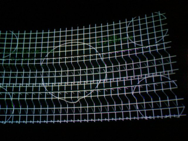
edit: I should have added the 4 pics in revers order
| Description: |
| spare point board installed and enabled - is this one broke too? |
|
| Filesize: |
68.18 KB |
| Viewed: |
10710 Time(s) |
|
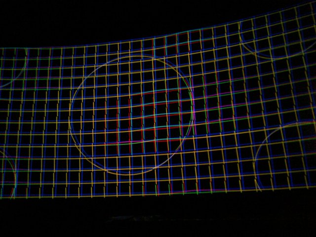
| Description: |
| original point board with awkward picture distortion, bended zones, flipping when settings are changed |
|
| Filesize: |
63.03 KB |
| Viewed: |
10709 Time(s) |
|
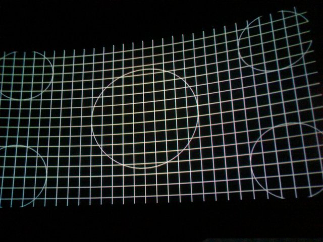
| Description: |
| point convergence disabled - no problem but poor convergence (can't be seen on mobile phone photo) |
|
| Filesize: |
66.4 KB |
| Viewed: |
10709 Time(s) |
|
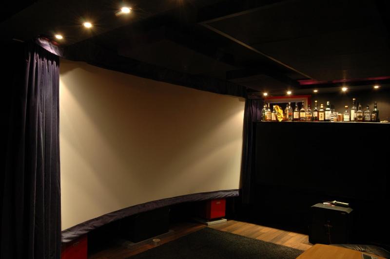
| Description: |
| curved screen with lights on |
|
| Filesize: |
51.65 KB |
| Viewed: |
10709 Time(s) |
|
_________________
HansA, alles andere ist euer Bier!
|
|
| Back to top |
|
 |
Curt Palme
CRT Tech
Joined: 08 Mar 2006
Posts: 24396
Location: Langley, BC
TV/Projector: All of them!
|
| Posted: Fri Mar 01, 2013 2:01 pm Post subject: |
|
|
Nice screen! 
LEaking caps on the point board, and I'll bet the other boards in teh CPU cage aren't far behind. Chances are there's some traces on the point board that have been eaten away. THere's about a 50% chance you can fix it if you're good at soldering. I personally won't look at it as there's no guarantee that the board won't fail again shortly.
I think I do have a good board here that I'd sell at $100 plus shipping if you can't get that one going.
|
|
| Back to top |
|
|
hansilili
Joined: 09 Mar 2007
Posts: 302
Location: Köln, Germany
|
| Posted: Fri Mar 01, 2013 2:19 pm Post subject: |
|
|
My spare board is supposed to be good too. Would have to reassemble the spare machine to test it though. That is why I ask if the point board is really the only thing to look after.
I am not good at soldering but if nothing else helps I can at least give it a try. It can't get any worse (okay, it probably can) Only first I would like to confirm that this is really what I am looking for.
UNfortunatly no spares for the other system cage boards around, only have plain Pg boards left.
THE PRoJECTOR IS IN A HUSHBOX without the outer case. All fans have been changed for new ones, some added. None yet for the system cage. Do you think the lid on the cage serves any real purpose or can I remove it and add a couple of small fans instead?
_________________
HansA, alles andere ist euer Bier!
|
|
| Back to top |
|
|
Curt Palme
CRT Tech
Joined: 08 Mar 2006
Posts: 24396
Location: Langley, BC
TV/Projector: All of them!
|
| Posted: Fri Mar 01, 2013 2:29 pm Post subject: |
|
|
Take the lid off. Also take the cover over the system boards off. I notice that the later PG Xtras have much bigger holes in the cover than the PG and PG+.
I've only ever seen the point board cause this. Once caps start leaking, they will continue to do so, even if not used. I've put away PG boards in good shape, only to pull them out 2 years later and then they are defective. I've seen this exact picture a number of times, and it's always been the point board.
|
|
| Back to top |
|
|
hansilili
Joined: 09 Mar 2007
Posts: 302
Location: Köln, Germany
|
|
| Back to top |
|
|
gjaky
Joined: 05 Jun 2010
Posts: 2802
Location: Budapest, Hungary
|
| Posted: Fri Mar 01, 2013 6:32 pm Post subject: |
|
|
We ran to a similar problen on my boss' 9PG, we've swapped it to a spare board and it works fine since, so I'd bet on point board only.
_________________
projectors in the past : NEC 6-9PG xtra, Electrohome Marquee 6-7500, NEC XG 1351 LC ( with super modified Electrohome VNB neckboard !!!)
current: VDC Marquee 9500LC
The MOD: VNB-DB, VIM-DB
|
|
| Back to top |
|
|
hansilili
Joined: 09 Mar 2007
Posts: 302
Location: Köln, Germany
|
| Posted: Tue Mar 05, 2013 7:47 am Post subject: |
|
|
Guy,
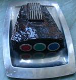
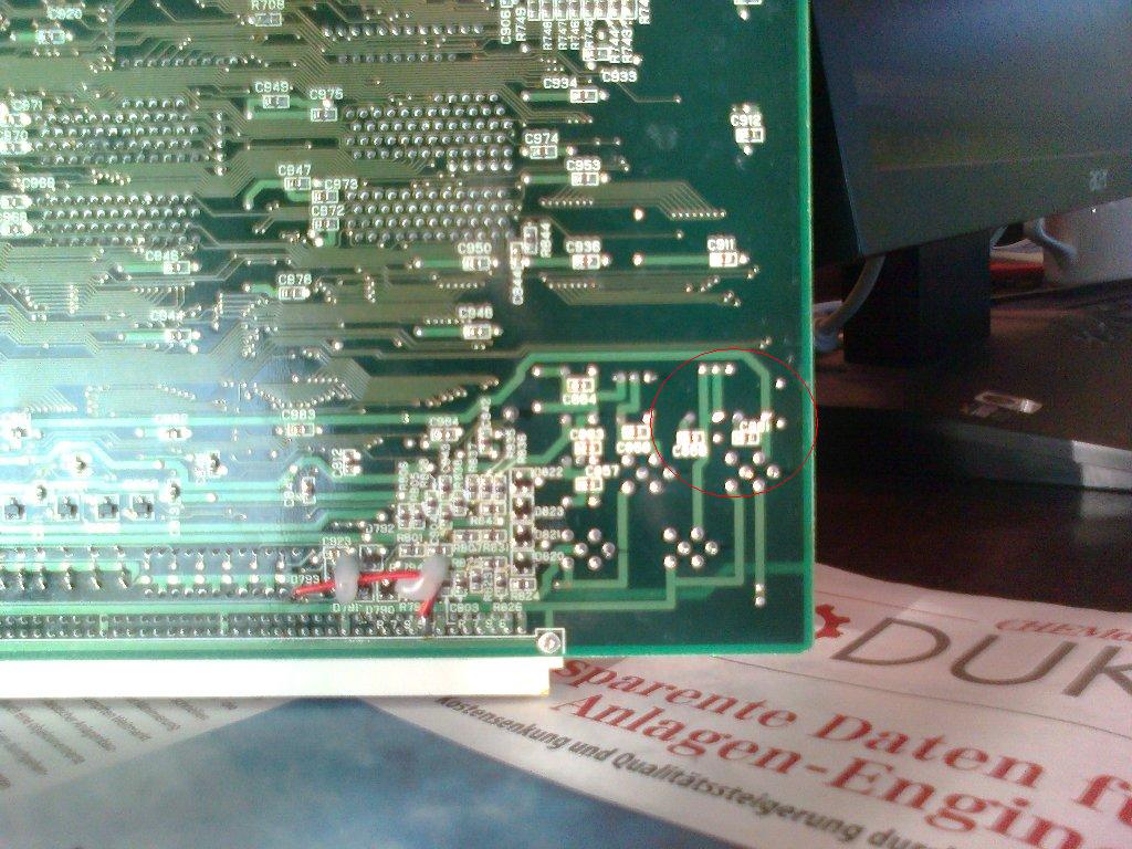
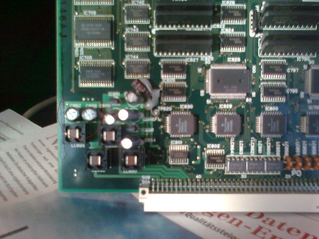
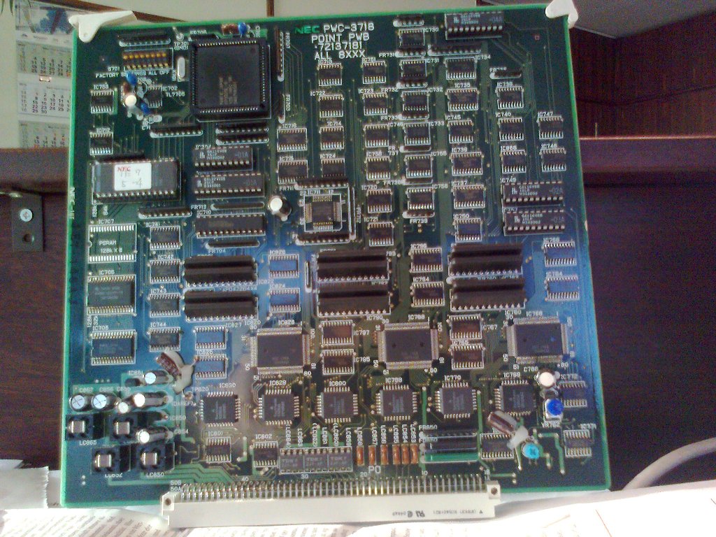
this is my PWC-3718. In zhe close up pics I have circled the two caps that were a little wet. On the front they are labled C862 and C856, on the back that's C861 and C859.
At least those two seem to be doable, even for a double lefty like me. Would be good to have a parts list for the whole board though.
will keep you posted
hanslilili
| Description: |
|
| Filesize: |
152.19 KB |
| Viewed: |
10593 Time(s) |
|
| Description: |
|
| Filesize: |
239.51 KB |
| Viewed: |
10593 Time(s) |
|
| Description: |
|
| Filesize: |
135.98 KB |
| Viewed: |
10985 Time(s) |
|
| Description: |
|
| Filesize: |
221.26 KB |
| Viewed: |
10593 Time(s) |
|
_________________
HansA, alles andere ist euer Bier!
|
|
| Back to top |
|
|
gjaky
Joined: 05 Jun 2010
Posts: 2802
Location: Budapest, Hungary
|
| Posted: Tue Mar 05, 2013 11:18 am Post subject: |
|
|
As you can see only a dozen electrolytics caps on the board, no list needed, just replace the caps with a same new one. On this board it is highly suggested that cut the bad caps off and solder the new caps on the old caps' legs, because the 4 layer PCB is very sensitive and hard to solder without a good equipment.
_________________
projectors in the past : NEC 6-9PG xtra, Electrohome Marquee 6-7500, NEC XG 1351 LC ( with super modified Electrohome VNB neckboard !!!)
current: VDC Marquee 9500LC
The MOD: VNB-DB, VIM-DB
|
|
| Back to top |
|
|
hansilili
Joined: 09 Mar 2007
Posts: 302
Location: Köln, Germany
|
| Posted: Tue Mar 05, 2013 1:33 pm Post subject: |
|
|
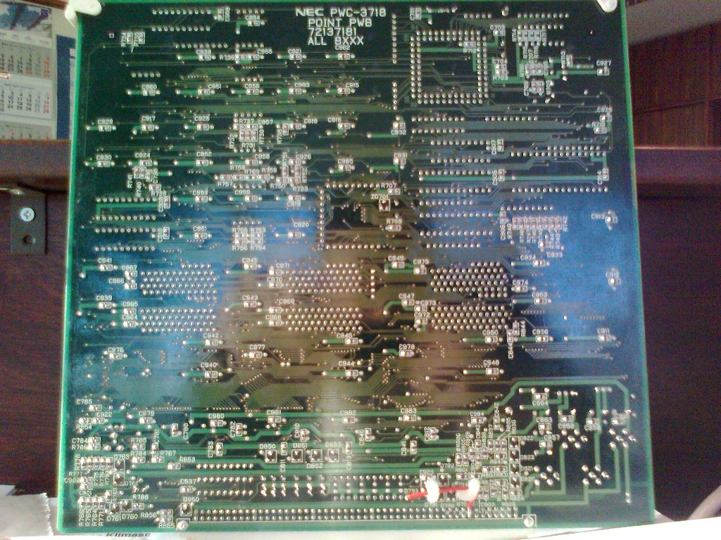
The PWC-3718 board has 11 caps, 5 x 100uF 16 V , 4 x 100uF 25V and 2 x 10uF 25V (if I read correctly)
gjaki, can you tell a bit more about "4 layer" board? UNsoldering these caps looks rather easy to me, for sure easier than cutting the very short legs. Which tool to use for that? A thin saw blade? Fingernail scissors?
hansilili
_________________
HansA, alles andere ist euer Bier!
|
|
| Back to top |
|
|
Curt Palme
CRT Tech
Joined: 08 Mar 2006
Posts: 24396
Location: Langley, BC
TV/Projector: All of them!
|
| Posted: Tue Mar 05, 2013 2:04 pm Post subject: |
|
|
|
No, brute force! Grab each electrolytic with a pair of pliers and pull straight up. The leads will pull out of the caps, and then you can cut them down and solder new ones on. Once the soldering iron hits the electrolyte that has leaked onto the leads, you'll get a very familiar (in a while from now) smell that I completely associate with NEC PG sets.
|
|
| Back to top |
|
|
hansilili
Joined: 09 Mar 2007
Posts: 302
Location: Köln, Germany
|
| Posted: Tue Mar 05, 2013 2:25 pm Post subject: |
|
|
| Curt Palme wrote: | | Once the soldering iron hits the electrolyte that has leaked onto the leads, you'll get a very familiar (in a while from now) smell that I completely associate with NEC PG sets. |
So you're saying I should order the caps in 100 pcs packs each? Pulling the other three systemboards is easy but I really didn't plan to disassemble the complete projector. Used to lift the 6xtra with one hand while rolling a cigarette with the other, but the 10pg is heavier and I have grown older (gave up smoking last week too).
_________________
HansA, alles andere ist euer Bier!
|
|
| Back to top |
|
|
hansilili
Joined: 09 Mar 2007
Posts: 302
Location: Köln, Germany
|
| Posted: Tue Mar 05, 2013 3:50 pm Post subject: |
|
|
| hansilili wrote: | Guy,
this is my PWC-3718. In zhe close up pics I have circled the two caps that were a little wet. On the front they are labled C862 and C856, on the back that's C861 and C859.
At least those two seem to be doable, even for a double lefty like me. Would be good to have a parts list for the whole board though.
will keep you posted
hanslilili |
The SMD ceramic capacitors 50V 0,1uF on the back, I guess no need to exchange them . Right?
_________________
HansA, alles andere ist euer Bier!
|
|
| Back to top |
|
|
Zolzar
Joined: 26 Jun 2009
Posts: 252
|
| Posted: Tue Mar 05, 2013 5:50 pm Post subject: |
|
|
No need to change the SMDs. I just did 350 caps in my 10PG. I had pretty decent success pulling them up with the needle nose but actually used a set of precision low profile cutters to cut the leads close to the body of the old cap as possible. I will reiterate what others have said and that is do not attempt to desolder any caps on any boards. The only ones I desoldered were on the focus and convergence boards.
I found that at least 100 caps out of the 350 were leaking. Many showed no evidence until they were removed.
Best of luck!
John
|
|
| Back to top |
|
|
CasetheCorvetteman

Joined: 09 Nov 2008
Posts: 6326
Location: Australia
|
| Posted: Wed Mar 06, 2013 12:33 am Post subject: |
|
|
| Curt Palme wrote: | | No, brute force! Grab each electrolytic with a pair of pliers and pull straight up. The leads will pull out of the caps, and then you can cut them down and solder new ones on. Once the soldering iron hits the electrolyte that has leaked onto the leads, you'll get a very familiar (in a while from now) smell that I completely associate with NEC PG sets. |
Absolutely.
|
|
| Back to top |
|
|
hansilili
Joined: 09 Mar 2007
Posts: 302
Location: Köln, Germany
|
| Posted: Fri Mar 15, 2013 8:50 am Post subject: |
|
|
So
yesterday we soldered together with a buddy. He is kinda experienced or should I say was experienced in the good old times so he said, "Soldering onto the old legs, nah, you just son't do that."
The first two and most suspicious capacitors actually went out quite well. A bit of good will helped but no brute force needed. This action seemed to have been successful, because of the onset of two new caps the board showed exactly the same behavior as before when tested in the projector . Phew, at least we didn't make it worse.
So we ventured to the next 4 candidates. This time there are sitting very small traces closely at the contacts. And unfortunately, this time we were not quite so lucky. After installing the"repaired" board and starting the projector the status of standby LED (Brown) to power (green) changes and you can hear a faint clicking atca. 2 Hz, but nothing else happens. We better should have listend to you guys and leave th eold legs in place. Without the point board however, the NEC running as before.
Without really have a clue I guess on a ground fault, since the click sounded like a fault interrupter. However, the display shows no error message. Ground faults to the newly soldered contacts should be detectable with a simple multitester, right? I will searching next week or so.
sh*t, I would have taken the time to print out the advice from a fellow German HT board member and meditate a bit about it:
| Quote: |
It's important is not to work with a too small soldering iron. The GND layer takes away a lot of heat. And if drawn out of a non-hot suffice cap leg the Via goes out with it. Then you have a small problem, broken link to middle layer.
The most important point in the action, however, is to make the circuit board clean. Since absolutely no electrolyte residues may remain longer. The leaked electrolyte creeps in the vias and other components, leading to the destruction of the conductors continuously, and the next failure is inevitable!
What damage the electrolytic capacitors have done to the tracks already? Sometimes that can not be seen directly. If e.g. the connection of a via or sleeve in Via is interrupted, you can find that out only by resistive measurements. Any discoloration on the board may be an indication. |
No risk, no fiasco
Greeting
rumpeli
_________________
HansA, alles andere ist euer Bier!
|
|
| Back to top |
|
|
hansilili
Joined: 09 Mar 2007
Posts: 302
Location: Köln, Germany
|
| Posted: Tue Mar 26, 2013 12:53 pm Post subject: |
|
|
Hi,
while exchanging the 6 caps we indeed fabricated a ground fault. This was identified by a budget multimeter resistance measurement very easy, as it was the only one with 0 ohm resistance! Slight rework of the soldering connection has eliminated the ground fault. So the projector is starting up as before the operation but the point convergence function is still not restored looks exactly like before the cap change
I give up. If you want, I will send the defective board. However, without the expectation of a concrete repair chance.
Please keep your eyes open for a 45 EUR / $60 point board incl. shipping to Germany. Oh, I will be visiting New York in May and could smuggle the board in my luggage.
Thanks
hansili.
_________________
HansA, alles andere ist euer Bier!
|
|
| Back to top |
|
|
CasetheCorvetteman
Joined: 09 Nov 2008
Posts: 6326
Location: Australia
|
| Posted: Tue Mar 26, 2013 1:34 pm Post subject: |
|
|
You were warned!! 
Couldve been worse...
|
|
| Back to top |
|
|
CasetheCorvetteman
Joined: 09 Nov 2008
Posts: 6326
Location: Australia
|
| Posted: Sat Jun 01, 2013 11:13 am Post subject: |
|
|
Sure, thats fine, and normally you wouldnt. But in this case, its a nice safe quick easy option that works 
|
|
| Back to top |
|
|
Curt Palme
CRT Tech
Joined: 08 Mar 2006
Posts: 24396
Location: Langley, BC
TV/Projector: All of them!
|
| Posted: Sat Jun 01, 2013 2:56 pm Post subject: |
|
|
|
$100 incl shipping to NY is as good as I can do.
|
|
| Back to top |
|
|
CasetheCorvetteman
Joined: 09 Nov 2008
Posts: 6326
Location: Australia
|
| Posted: Sat Jun 01, 2013 5:44 pm Post subject: |
|
|
|
And thats pretty good anyway
|
|
| Back to top |
|
|
|
|


