|
As this forum is rarely used anymore, we've locked it. Feel free to browse and read. Questions? Please reach out to us directly. Cheers! |

|
 |
|
|
| Author |
Message |
Nashou66

Joined: 12 Jan 2007
Posts: 16171
Location: West Seneca NY
|
|
| Back to top |
|
 |
gjaky
Joined: 05 Jun 2010
Posts: 2802
Location: Budapest, Hungary
|
| Posted: Thu Oct 25, 2012 8:42 pm Post subject: |
|
|
| CIR Engineering wrote: | Try looking at a 30 IRE window from your seating position.
craigr |
That looks fine, the ringing is very-very faint, I can only see if I really look for it.
_________________
projectors in the past : NEC 6-9PG xtra, Electrohome Marquee 6-7500, NEC XG 1351 LC ( with super modified Electrohome VNB neckboard !!!)
current: VDC Marquee 9500LC
The MOD: VNB-DB, VIM-DB
|
|
| Back to top |
|
|
CIR Engineering

Joined: 25 Aug 2008
Posts: 4269
Location: Chicago USA & Berlin Germany
|
| Posted: Thu Oct 25, 2012 9:11 pm Post subject: |
|
|
What does the adjustable blanking voltage do?
craigr
_________________
JETI 1501-HiRes 2nm Spectroradiometer
JETI 1211 Spectroradiometer
Photo Research PR-650 Spectroradiometer
Klein K10-A Colorimeter
Murideo Fresco SIX-G HDMI 2.x Multimedia Generator
Murideo Fresco SIX-A HDMI 2.x Analyzer
Light Illusion ColourSpace XPT Color Calibration Software
Light Illusion LightSpace XPT Pro Version 10.x Color Calibration Software
OMARDRIS JVC Software Patch to use K10-A and Jeti with JVC OEM AutoCal Software!
Sencore CR7000 CRT Tube Analyzer / Rejuvenater
Authorized Dealer for Lumagen & just about everything worth buying 
www.CIR-Engineering.com - craigr@cir-engineering.com
Phone: 865-405-6892
|
|
| Back to top |
|
|
gjaky
Joined: 05 Jun 2010
Posts: 2802
Location: Budapest, Hungary
|
| Posted: Thu Oct 25, 2012 9:33 pm Post subject: |
|
|
| CIR Engineering wrote: | What does the adjustable blanking voltage do?
craigr |
Believe or not it affect brightness.
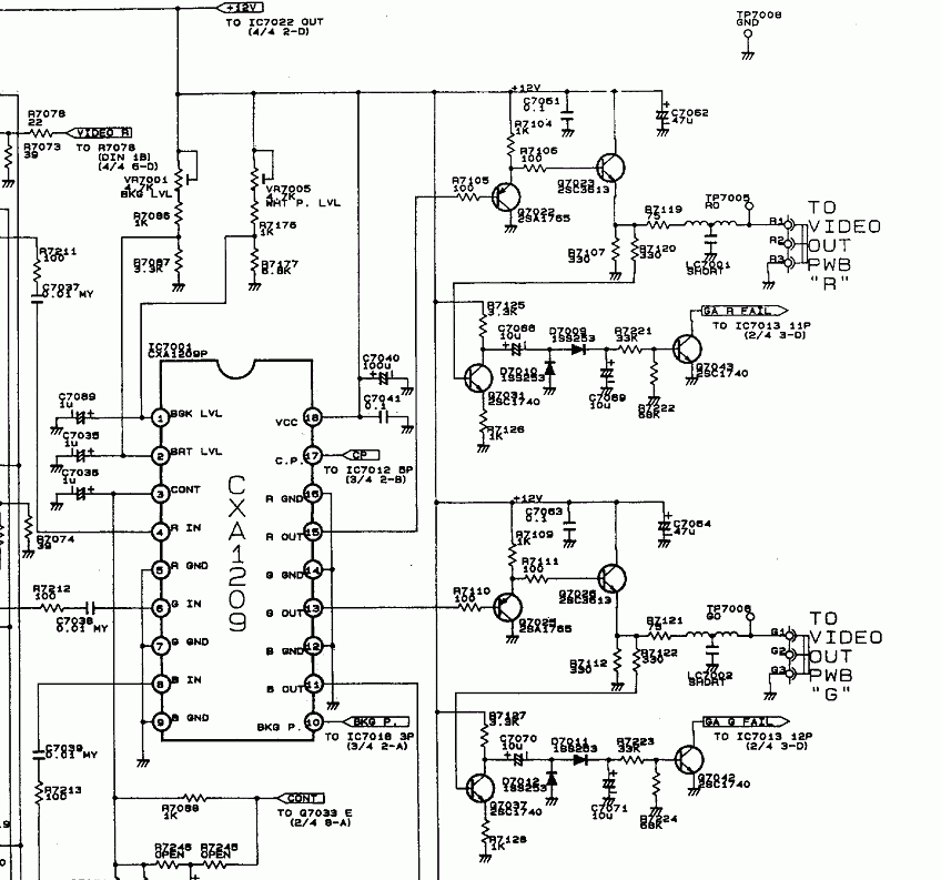
Attached the corresponding page of the circuit diagram.
| Description: |
|
| Filesize: |
75.07 KB |
| Viewed: |
8627 Time(s) |
|
_________________
projectors in the past : NEC 6-9PG xtra, Electrohome Marquee 6-7500, NEC XG 1351 LC ( with super modified Electrohome VNB neckboard !!!)
current: VDC Marquee 9500LC
The MOD: VNB-DB, VIM-DB
|
|
| Back to top |
|
|
CIR Engineering
Joined: 25 Aug 2008
Posts: 4269
Location: Chicago USA & Berlin Germany
|
| Posted: Thu Oct 25, 2012 10:26 pm Post subject: |
|
|
I thought so, but I can't understand why anyone would want this?
craigr
_________________
JETI 1501-HiRes 2nm Spectroradiometer
JETI 1211 Spectroradiometer
Photo Research PR-650 Spectroradiometer
Klein K10-A Colorimeter
Murideo Fresco SIX-G HDMI 2.x Multimedia Generator
Murideo Fresco SIX-A HDMI 2.x Analyzer
Light Illusion ColourSpace XPT Color Calibration Software
Light Illusion LightSpace XPT Pro Version 10.x Color Calibration Software
OMARDRIS JVC Software Patch to use K10-A and Jeti with JVC OEM AutoCal Software!
Sencore CR7000 CRT Tube Analyzer / Rejuvenater
Authorized Dealer for Lumagen & just about everything worth buying
www.CIR-Engineering.com - craigr@cir-engineering.com
Phone: 865-405-6892
|
|
| Back to top |
|
|
gjaky
Joined: 05 Jun 2010
Posts: 2802
Location: Budapest, Hungary
|
| Posted: Sat Oct 27, 2012 8:16 am Post subject: |
|
|
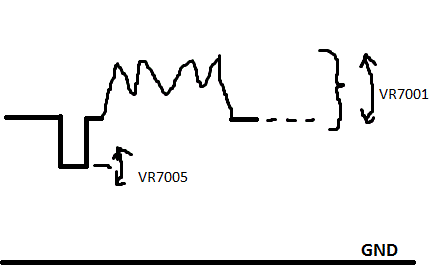
I'm sure that those crafty japanese engineers who designed the NEC had a good reason to do it this way.
Since the next stage at the VIDEO OUT board is AC coupled, it is obvious that the key is not in the absolute level of blanking, but the difference between pedestal level and blanking level, The output buffer (consist of the two transistor) should work at any DC level. With the new IC the minimal output pedestal level is at about 1,2V, the blanking level is fixed at 0,2V so the difference is about 1V. This is with the original IC: pedestal at 2,3V blanking at 2,1V so the difference is 0,2V with the original IC, I have to do some experiments to find out is there any way to compensate the brightness increase caused in GAIN CTL (without massive recalibration on the VIDEO OUT board...)
Finally I had the chance to get NEC XG schematic diagrams, to look at what they did differently (I assumed the basic design approach didn't change a lot) So I started the first series' (XG ***0) schematics.
The neck boards are *almost* the same between XG0 and PG xtra, both based on a single VPA13 (130MHz) video amp (some more transistors on XG's though)
On VIDEO OUT board both type use the same LM1201 (200MHz) ic in very similar configuration.
Aaand the best part: On XG's GAIN CTL the main IC is the CXA1779P, this is exactly the same what I am trying to fitting in the PG now -and didn't even knew this was used in XG, funny 
I should look for hints in XG schematics for implementation of the new IC.
On a side note I have to add, that the last series of XG has a more complicated RGB path: CXA1779P->CXA1709P (250MHz)-> dual VPA13 neck boards
| Description: |
| Effect of the two trimmers on output signal |
|
| Filesize: |
3.8 KB |
| Viewed: |
8586 Time(s) |
|
_________________
projectors in the past : NEC 6-9PG xtra, Electrohome Marquee 6-7500, NEC XG 1351 LC ( with super modified Electrohome VNB neckboard !!!)
current: VDC Marquee 9500LC
The MOD: VNB-DB, VIM-DB
|
|
| Back to top |
|
|
CasetheCorvetteman

Joined: 09 Nov 2008
Posts: 6326
Location: Australia
|
| Posted: Sat Oct 27, 2012 2:35 pm Post subject: |
|
|
|
I hope you dont burn the tubes with this extra level there.
|
|
| Back to top |
|
|
gjaky
Joined: 05 Jun 2010
Posts: 2802
Location: Budapest, Hungary
|
| Posted: Sat Oct 27, 2012 7:37 pm Post subject: |
|
|
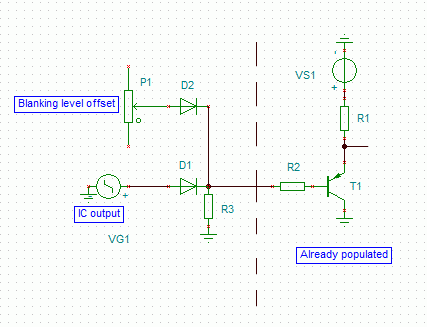
Craig, what do you think about this one? Please look at the attached schematic, the diode system would not let the output go "lower" than the 'blanking level', but I am not sure if a simple 1N4148 would do the job, or should I need a super fast diode?
| Description: |
| CXA1779 blanking level adjutment trick |
|
| Filesize: |
5.18 KB |
| Viewed: |
8555 Time(s) |
|
_________________
projectors in the past : NEC 6-9PG xtra, Electrohome Marquee 6-7500, NEC XG 1351 LC ( with super modified Electrohome VNB neckboard !!!)
current: VDC Marquee 9500LC
The MOD: VNB-DB, VIM-DB
|
|
| Back to top |
|
|
hansilili

Joined: 09 Mar 2007
Posts: 302
Location: Köln, Germany
|
| Posted: Wed Nov 07, 2012 2:45 pm Post subject: |
|
|
I think I have a bandwidth issue sinse modding my 10PG with PG6100 parts. The 10PGplus does not sync on 1080P60 and with 1080P50 resolution, the horisontal lines are much much better resolved than the vertical ones (as describe above). My AVR puts out 60 Hz by default so it would be convenient if the projetor could handel this ( HTPC-HDMIout->AVRHDMIout->HDFuryVGAout-10PGplus). Also I think 60Hz could improve picture stutter with 1080i60 BluRays.
Since then I am looking for a PG9100 board donor but these are ultra rare. Until then video is fed from PC VGA out to the projector directly with 2100*933 @50Hz (because of my awkward screen aspect ratio).
1. Do you think more bandwidth would improve picture quality with current 933P50 resolution?
2. Would your mod add bandwigth to my 10PGplus, which is mostly a 6PGplus
3. Can you prepare a foto documented tutorial for the soldering job?
BTW good to see some serious technical discussions going on here besides the usual screen shot d**k swinging pi**ing contest.
Cheers
hansilili
_________________
HansA, alles andere ist euer Bier!
|
|
| Back to top |
|
|
gjaky
Joined: 05 Jun 2010
Posts: 2802
Location: Budapest, Hungary
|
| Posted: Wed Nov 07, 2012 4:02 pm Post subject: |
|
|
| hansilili wrote: | I think I have a bandwidth issue sinse modding my 10PG with PG6100 parts. The 10PGplus does not sync on 1080P60 and with 1080P50 resolution, the horisontal lines are much much better resolved than the vertical ones (as describe above). My AVR puts out 60 Hz by default so it would be convenient if the projetor could handel this ( HTPC-HDMIout->AVRHDMIout->HDFuryVGAout-10PGplus). Also I think 60Hz could improve picture stutter with 1080i60 BluRays.
Since then I am looking for a PG9100 board donor but these are ultra rare. Until then video is fed from PC VGA out to the projector directly with 2100*933 @50Hz (because of my awkward screen aspect ratio).
1. Do you think more bandwidth would improve picture quality with current 933P50 resolution?
2. Would your mod add bandwigth to my 10PGplus, which is mostly a 6PGplus
3. Can you prepare a foto documented tutorial for the soldering job?
BTW good to see some serious technical discussions going on here besides the usual screen shot d**k swinging pi**ing contest.
Cheers
hansilili |
I think 1080p60Hz is too much for PG plus since it scans to 65kHz, and 1080p60Hz needs about 67kHz (my 6PG xtra scans to 69kHz, and just accepts 1080p60Hz), so ideally you should get a "H-sync over limit" message with that, but the picture should not be scrambled. While 1080p50Hz needs about 57kHz, which is well within the 6PG+'s specs, so you probably have bad caps somewhere on the deflection board, or in the input section (maybe system board affected too), OR your deflection board needs to be recalibrated according to the service manual's guidline.
Once your picture is not scrambled then you could step forward: the maximal H-scan is limited in two places in the set. Once there is the big black custom IC on the deflection board. The one called FVA is for the 6PG series (these are the same for all PGs!) and FVB is for 9PG series, swapping this ic will allow the def board to operate at scanrates over 70kHz -I have done this once and works fine since then. Unfortunately the system board also limits the maximal scanrate, but I never really tried to find out how it works, it may or may not be fooled, otherwise replacing the system board from a 9PG+ is the only solution.
This has nothing to do with picture quality and bandwidth.
The RGB path is very similar in all PGs, the biggest difference is the different video amplifier in PG xtra.
In the case of PG plain and plus the CRT driver IC is a VPH06 which is only designed as a 65MHz chip while the specs are saying 70MHz for the whole machine, I'm not saying it can't even do the 70MHz, but it is sure the designers squeezed the sh!t out of that IC already, so in this case the input reception is far better than the signal path's end. Changing the output IC could help somewhat, for example the barco 120MHz neck boards are using the VPH08 chip which should be better somewhat.
BUT if I am correct you have a PG xtra chassis with bad tubes, I seem to remember we discussed earlier the opportunity of a 10PG xtra project, at that time I was disparaged since "it can't be done". In the meantime I found information about forum member 'Mark_A_W' managed to work E8505 red and blue tubes in a PG xtra, I don't know what was with the green though. So if you can get (or already have) a set of worn out E8505 tubes, then I'd play with them in the PG xtra chassis, once you managed them to work fine, you are ready for a 10PG xtra.
As for my project: still a lot of things to measure with my test circuits to make sure I can fit the new IC in and it will yeld any improvement.
I planned to share every information about the project when it will be finished.
_________________
projectors in the past : NEC 6-9PG xtra, Electrohome Marquee 6-7500, NEC XG 1351 LC ( with super modified Electrohome VNB neckboard !!!)
current: VDC Marquee 9500LC
The MOD: VNB-DB, VIM-DB
|
|
| Back to top |
|
|
CasetheCorvetteman
Joined: 09 Nov 2008
Posts: 6326
Location: Australia
|
| Posted: Wed Nov 07, 2012 11:50 pm Post subject: |
|
|
|
Why are you doing 2100 wide?
|
|
| Back to top |
|
|
hansilili
Joined: 09 Mar 2007
Posts: 302
Location: Köln, Germany
|
| Posted: Thu Nov 08, 2012 10:08 am Post subject: |
|
|
| CasetheCorvetteman wrote: | | Why are you doing 2100 wide? |
My screen is somewhere inbetween 16:9 and 21:9, 2100*933 gives the correct dektop aspect ratio for the screen.
933 lines is my compromise to fully resolve scope hd material and sacrifice some resolution for 16:9. The machine and jeopardized lens focus on curved screen does not reolve 1080P anyway.
I had two xtras which are both gone, now a have only two 10PG left. I have to look up that deflection board calibration thing, unfortunately I am not familiar with using an oszilloscope.
You say increase bandwidth would not increase resolution of vertical lines in my setup? I was referring to your statement:
| Quote: | Resolution pattern in 1080p, the horizontal lines are a touch tighter, than the vertical lines, so the focus is better than the bandwidth -so still not a bad idea to increase the bandwidth.
|
off topic: is there a pot for trimming the setting of the electronic bow adjustment? Mine is maxed out because of the curved screen.
Cheers
hansilili
_________________
HansA, alles andere ist euer Bier!
|
|
| Back to top |
|
|
CasetheCorvetteman
Joined: 09 Nov 2008
Posts: 6326
Location: Australia
|
| Posted: Thu Nov 08, 2012 10:39 am Post subject: |
|
|
Are your yokes connected correctly? Try flipping one of the 180° on the convergence board with the pin set to 0 and see what it does for you.
2100 wide is a big ask.
Youd be better off going 1920 wide and having boarders at the screen sides for 16:9 i reckon, youre missing a heap of lines top and bottom at the res youre running now.
|
|
| Back to top |
|
|
hansilili
Joined: 09 Mar 2007
Posts: 302
Location: Köln, Germany
|
| Posted: Thu Nov 08, 2012 12:17 pm Post subject: |
|
|
no no no no no
my screen is 3.42 x 1.52 m2 and curved, the projector is hanging too low and backward tiltetd because of low ceiling height! Yoke connection for ceiling setup is confirmed and correkt. Desktop setup changes bow setting too, but the overall adjustment for my curved ceiling projection ist better with ceiling setup of the machiine. I am maxing out pin balance and point convergence though.
Appreciate your input but it's really offtopic in this thread. Maybe better carry on in my HT built thread.
High horizontal picture source resolution does not bother the projector electronics. The higher (multiples of 1920) the better for picture quality because of reduced aliasing. However in practice this is irrelevant because the projector would not resolve aliasing anyway. Just for convenience I chose a source aspect ratio which suits my screen size.
It is only the number of lines which is limitied by electronic bandwidth. The more lines and the higher the frequency -> the faste the beam moves on the phospor, the more sreen resolution you loose from electronic bandwidth.
1080P60 is scrambled on my 10pg 6pgplus boards. In 1080P50, horizontal lines are thinner and sharper then vertical lines. Not so with 720P
_________________
HansA, alles andere ist euer Bier!
|
|
| Back to top |
|
|
CasetheCorvetteman
Joined: 09 Nov 2008
Posts: 6326
Location: Australia
|
| Posted: Thu Nov 08, 2012 11:57 pm Post subject: |
|
|
|
Start again from scratch, shouldnt need much pin balance if youre square to the screen center.
|
|
| Back to top |
|
|
barclay66

Joined: 27 Jun 2011
Posts: 1304
Location: Germany
TV/Projector: Marquee 9500 Ultra
|
| Posted: Fri Nov 09, 2012 1:02 am Post subject: |
|
|
| hansilili wrote: | | It is only the number of lines which is limitied by electronic bandwidth. |
Hi,
Are You sure?
Let's look at it from the perspective of the electron beam:
The electron beam is deflected by horizontal and vertical deflection coils. At 1080p60 the horizontal deflection works at a frequency of roughly 65kHz (movement from left to right) and the vertical deflection works at 60Hz (movement from top to bottom). The first is based on number of lines multiplied by number of frames per second (1,080 x 60 = 64,800) and the second is defined by the framerate itself (60 per second). So while the beam is deflected very fast from left to right it is deflected much more slowly from top to bottom. The result of the combination of both deflection systems is that the beam will "write" a frame line by line from top to bottom. So the vertical resolution is determined by the amount of lines that the combination of horizontal and vertical deflection rates will produce. There is a limitation involved which is called maximum scan rate. If the deflection electronics can't deal with the required scan rate, there won't be a stable picture.
In my opinion this hasn't anything to do with electronic bandwith.
Electronic bandwith comes into play when thinking about the maximum number of brightness intensity changes the beam can produce while being deflected. For 1080p the number of changes for a single line has to be at least 1,920 (HD resolution). And this amount of changes has to be performed for each line in a timeframe of 0.0000154 seconds (1/64,800)! And this tells us that the minimum frequency of changes (=bandwith of the video chain) has to be 124.41 MHz (1,920 / 0.0000154).
If the bandwith is lower, the electronics (=video amplifiers etc.) will "miss" changes within the source signal and will therefore produce a picture which is missing details although it might be able to produce a stable picture...
Regards,
barclay66
|
|
| Back to top |
|
|
CasetheCorvetteman
Joined: 09 Nov 2008
Posts: 6326
Location: Australia
|
| Posted: Fri Nov 09, 2012 1:49 am Post subject: |
|
|
|
Re run those numbers for his 2100 horizontal res.
|
|
| Back to top |
|
|
CasetheCorvetteman
Joined: 09 Nov 2008
Posts: 6326
Location: Australia
|
| Posted: Fri Nov 09, 2012 2:57 am Post subject: |
|
|
About 136MHz?
What is the limit on a PG Plus? 75MHz?
The 6 XTRA is 80MHz, so it would have to be less than that...
|
|
| Back to top |
|
|
gjaky
Joined: 05 Jun 2010
Posts: 2802
Location: Budapest, Hungary
|
| Posted: Fri Nov 09, 2012 11:33 am Post subject: |
|
|
| CasetheCorvetteman wrote: | About 136MHz?
What is the limit on a PG Plus? 75MHz?
The 6 XTRA is 80MHz, so it would have to be less than that... |
In addition: while the signal has 136MHZ bandwidth, the projectors are specified for bandwidth at -3dB point, at -3dB point the output amplitude is only about 70% of the refernece value, so at -3dB point you get significant, but still acceptable signal loss (in this case: resolution loss). This means if you have a 75MHz (-3dB) projector it is fully accomodate signals with only ~65-70MHz bandwidth.
If you use this calculator:
http://myhometheater.homestead.com/bandwidthcalculator.html
It gives directly the -3dB bandwidth requirement for minimal loss.
Case, I think the bandwidth of the 6PG xtra is not less by any MHz than the 9PG xtra's, I think it was just said to be 80MHz because of marketing reasons. The two set using exactly the same RGB path, more over exactly the same boards, no way there is any difference between them in performance. The only limitation was the lack of multi decoder board, lack of point convergence board, and the limited scanrate, which has nothing to do with signal bandwidth -as already said. This also applies to NEC XGs, they are rated between 110-150MHz depending on model, but all of them using exactly the same board in signal path, ditto for the electrohome marquees.
_________________
projectors in the past : NEC 6-9PG xtra, Electrohome Marquee 6-7500, NEC XG 1351 LC ( with super modified Electrohome VNB neckboard !!!)
current: VDC Marquee 9500LC
The MOD: VNB-DB, VIM-DB
|
|
| Back to top |
|
|
hansilili
Joined: 09 Mar 2007
Posts: 302
Location: Köln, Germany
|
| Posted: Fri Nov 09, 2012 12:22 pm Post subject: |
|
|
| barclay66 wrote: |
Are You sure?
Let's look at it from the perspective of the electron beam:
The electron beam is deflected by horizontal and vertical deflection coils. At 1080p60 the horizontal deflection works at a frequency of roughly 65kHz (movement from left to right) and the vertical deflection works at 60Hz (movement from top to bottom). The first is based on number of lines multiplied by number of frames per second (1,080 x 60 = 64,800) and the second is defined by the framerate itself (60 per second). So while the beam is deflected very fast from left to right it is deflected much more slowly from top to bottom. The result of the combination of both deflection systems is that the beam will "write" a frame line by line from top to bottom. So the vertical resolution is determined by the amount of lines that the combination of horizontal and vertical deflection rates will produce. There is a limitation involved which is called maximum scan rate. If the deflection electronics can't deal with the required scan rate, there won't be a stable picture.
In my opinion this hasn't anything to do with electronic bandwith.
Electronic bandwith comes into play when thinking about the maximum number of brightness intensity changes the beam can produce while being deflected. For 1080p the number of changes for a single line has to be at least 1,920 (HD resolution). And this amount of changes has to be performed for each line in a timeframe of 0.0000154 seconds (1/64,800)! And this tells us that the minimum frequency of changes (=bandwith of the video chain) has to be 124.41 MHz (1,920 / 0.0000154).
If the bandwith is lower, the electronics (=video amplifiers etc.) will "miss" changes within the source signal and will therefore produce a picture which is missing details although it might be able to produce a stable picture...
Regards,
barclay66 |
agree to most all you say, but not "For 1080p the number of changes for a single line has to be at least 1,920". 1920 is the max. of changes that can occur. Even if the pixel resolution of the HTPC is double 1920 (or 2100 as in my case) the scan frequency does not increase.
I thought we were all through this already in the first half of the last decade. Optimum scaling for CRT projectors has been discussed in depth. I learned the most from this thread and from salvechris (off line). barcalay can even read this but there were english translations here and on avs too, I just don't find the proper links.
hansilili
_________________
HansA, alles andere ist euer Bier!
|
|
| Back to top |
|
|
|
|
|
|
|
You cannot post new topics in this forum
You cannot reply to topics in this forum
You cannot edit your posts in this forum
You cannot delete your posts in this forum
You cannot vote in polls in this forum
You cannot attach files in this forum
You can download files in this forum
|
Forum powered by phpBB © phpBB Group
|
|


