|
As this forum is rarely used anymore, we've locked it. Feel free to browse and read. Questions? Please reach out to us directly. Cheers! |
|
 |
|
|
| Author |
Message |
mc86
Joined: 20 Sep 2008
Posts: 767
Location: pittsburgh, pa
TV/Projector: ECP 4500 (Vidikron box), ECP4500+, wanting 07MS/07MTS, evaluating pc soft-blend
|
| Posted: Tue Apr 10, 2012 9:30 pm Post subject: Arcane wear Q regarding Red/Blue tubes |
|
|
All -
I was just re-reading part of my ECP manual and did a little "huh" to myself at the fact that the Waveform Module "provides a small ramp in gain of the red and blue colors over the horizontal weep range to compensate for the luminosity differences of these colors between the left and right side of the image." Out of curiosity, I read the G90 "Theory of Operation" document and see it implements the same sawtooth correction as well.
Who am I to doubt their engineers, but is this really needed? If so, I'd think one side of the tube would wear faster than the other...but I've never seen a wear pattern picture that shows the left or right side of a blue/red tube that looked very different. Certainly the percentage could only be a few percent (the same fraction in area difference from a differential left vs right edge) -- would that be noticeable onscreen? Seems very strange to me.
Cheers,
Matt
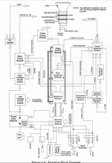
BTW, the function block diagram for the ECP (attached) is really nice -- Is there a similar overview schematic for a high-end 9" machine. The G90 theory of operation is VERY clear for sub-components and the video/sync chain, but does not provide an overall system schematic. I looked around (quickly) at various manufacturers 9"units and didn't see anything. I was hoping to try to do an overlay of sorts so I could see what sophisticated layers were added to my "simple" machine's circuitry. You folks said ECP was a great place to start learning...!
| Description: |
|
| Filesize: |
48.77 KB |
| Viewed: |
3605 Time(s) |
|
|
|
| Back to top |
|
 |
macgyver655
Joined: 22 Aug 2007
Posts: 8508
|
| Posted: Tue Apr 10, 2012 10:02 pm Post subject: |
|
|
|
The gain difference is to balance out not increase one side. And your wear question would only apply on a constant full white screen. For video the entire screen of any color is not consistently used.
|
|
| Back to top |
|
|
Nashou66

Joined: 12 Jan 2007
Posts: 16171
Location: West Seneca NY
|
|
| Back to top |
|
|
Tim in Phoenix

Joined: 21 Oct 2006
Posts: 4409
Location: Phoenix
|
| Posted: Wed Apr 11, 2012 6:23 pm Post subject: |
|
|
| Nashou66 wrote: | The Marquee theory of operation is also well written . I think I must have read that manual 100 times, and each time I would have an AHH HAA Moment . Matt you need a Marquee buddy !
Athanasios |
Yeah, tons more adjustments to mess with!!!!!!!
.
|
|
| Back to top |
|
|
ChrisWiggles
Opinionated SOB
Joined: 12 Mar 2006
Posts: 2529
Location: Seattle
|
| Posted: Thu Apr 12, 2012 12:10 am Post subject: |
|
|
It's not for wear but for the angle of the tubes. Guy Kuo covered this a long time ago in his holy focus guide, in the portion where he discusses whether to align the center of the tubes, or the outside edges of the tubes. If you align the outside edges, the angle is less and so you have less of the trapezoidal shift and hence less light drop as you move to the far side of the screen. You have to think of it as a beam of light hitting a plane at an angle. The far side uses less of the tube face because it spreads out and so light output is less. The near side uses more. Both compared to what the green tube uses in the middle which is equal side-to-side because it's not angled.
Does that make sense? It's a little bit weird to explain. But basically it helps reduce subtle color-shifting (even on a matte surface with no gain) where the nearer side tube gets you more light (slightly more blue on one side, slightly more red on the other).
|
|
| Back to top |
|
|
mc86
Joined: 20 Sep 2008
Posts: 767
Location: pittsburgh, pa
TV/Projector: ECP 4500 (Vidikron box), ECP4500+, wanting 07MS/07MTS, evaluating pc soft-blend
|
| Posted: Thu Apr 12, 2012 4:21 am Post subject: |
|
|
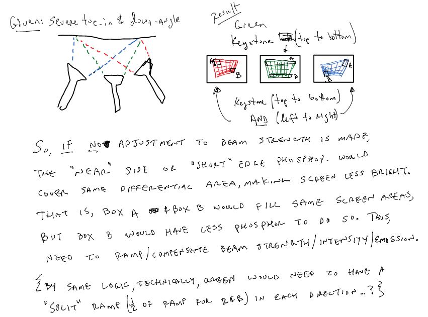
Chris -- Thanks for weighing-in as well. I think I'm having a hard time expressing my thoughts. I've been holding off replying as I want to see if I can get this out so you guys can set me straight! I understand the ramp is applied not to compensate for uneven wear -- it is applied to make the on-screen image correct. I considered the ideal case of Mac's hypothetical constant, full-white screen...
1) Goal: the PJ should be able to display a uniform intensity white image over the entire projected surface.
2) Problem: the R&B tubes "toe-in". IF the beam swept with a constant gain over the phosphor area, the luminous emittance would be constant. As such, one would find the on-screen illuminance would be non-uniform due to the fact that unequal areas of phosphor transmit to equal areas of screen...i.e., keystoning the image on the tube face is required.
3) Fix: apply a gradient or ramp to the beam strength/gain as the beam sweeps from edge to edge of the tubes. For R&B, these would be of opposing signs (increasing R to L in one, L to R in the other). Point being, the phosphor on the tube face does NOT have a constant luminous emittance to insure the illuminance IS constant.
4) Implications: one side (and I suppose the top and bottom given all tubes equally keystone vertically) of both the red and blue tubes is always driven a little harder than the other side. Thus, shouldn't the tubes' phosphor wear unevenly on their faces? And if not, doesn't this imply the need for accounting for this is -- under correct/normal installations -- not significant or detectable by human visual acuity?
Attached is a sketch I made in my notebook for myself, but maybe shows my thinking a bit better (the text in the image does not). Again, I feel like I must be wrong on something obvious, just not seeing where it is.  OR possibly this is a really minor effect that a design engineer worried about when he/she really shouldn't have bothered. Help! OR possibly this is a really minor effect that a design engineer worried about when he/she really shouldn't have bothered. Help!
cheers,
Matt
| Description: |
| exaggerated toe-in/vertical angle |
|
| Filesize: |
81.37 KB |
| Viewed: |
3515 Time(s) |
|
|
|
| Back to top |
|
|
Nashou66
Joined: 12 Jan 2007
Posts: 16171
Location: West Seneca NY
|
| Posted: Thu Apr 12, 2012 11:46 am Post subject: |
|
|
I think the distance in the tube itself for the electron beam may have something to do with it. it travels further to get to the edges , and maybe less energy so it has to be increased towards the edges. Just hypothesizing here. I know that the amount of vacuum also plays into the distance a beam can travel at full intensity. So maybe that has something to do with it. Also take into consideration the Lens itself, and the shape of the beam spot size at the edges all of which are not as defined as at the center. They might have had to compensate for this. Marquees have a zone contrast modulation to compensate for this.
Everything Chris said is correct as well, so it might be a little bit of everything.
EDIT: here is a cool link on home made CRT's he talks about vacuum and distance:
http://www.sparkbangbuzz.com/crt/crt6.htm
And another interesting read:
http://celco-nj.com/SID_Paper01.htm
Athanasios
_________________
Don't blame your underwear for your crooked ass~ unknown Greek philosopher
"Republicans believe every day is the Fourth of July, but the Democrats believe every day is April 15." --- President Reagan
One Smart Dog!!!
Marquee High Performance Bellows now shipping!!
Marquee Modifications and Performance Enhancement
Marquee C-element and Bellow removal
|
|
| Back to top |
|
|
ChrisWiggles
Opinionated SOB
Joined: 12 Mar 2006
Posts: 2529
Location: Seattle
|
| Posted: Thu Apr 12, 2012 6:53 pm Post subject: |
|
|
| mc86 wrote: | Chris -- Thanks for weighing-in as well. I think I'm having a hard time expressing my thoughts. I've been holding off replying as I want to see if I can get this out so you guys can set me straight! I understand the ramp is applied not to compensate for uneven wear -- it is applied to make the on-screen image correct. I considered the ideal case of Mac's hypothetical constant, full-white screen...
1) Goal: the PJ should be able to display a uniform intensity white image over the entire projected surface.
2) Problem: the R&B tubes "toe-in". IF the beam swept with a constant gain over the phosphor area, the luminous emittance would be constant. As such, one would find the on-screen illuminance would be non-uniform due to the fact that unequal areas of phosphor transmit to equal areas of screen...i.e., keystoning the image on the tube face is required.
3) Fix: apply a gradient or ramp to the beam strength/gain as the beam sweeps from edge to edge of the tubes. For R&B, these would be of opposing signs (increasing R to L in one, L to R in the other). Point being, the phosphor on the tube face does NOT have a constant luminous emittance to insure the illuminance IS constant.
4) Implications: one side (and I suppose the top and bottom given all tubes equally keystone vertically) of both the red and blue tubes is always driven a little harder than the other side. Thus, shouldn't the tubes' phosphor wear unevenly on their faces? And if not, doesn't this imply the need for accounting for this is -- under correct/normal installations -- not significant or detectable by human visual acuity?
Attached is a sketch I made in my notebook for myself, but maybe shows my thinking a bit better (the text in the image does not). Again, I feel like I must be wrong on something obvious, just not seeing where it is. OR possibly this is a really minor effect that a design engineer worried about when he/she really shouldn't have bothered. Help!
cheers,
Matt |
Yes but I think you have the A and B backwards. (I love the drawing btw!)
I'm a little confused because I don't know if the trapezoidal drawings is looking into the lenses (backwards-oriented) or what it would look like at the screen uncompensated.
But I do think you have it backwards because the near side uses MORE phosphor, and is brighter. The FAR side uses less phosphor and is dimmer. That's why you have to do the trapezoid compensation to shrink the far/opposite side down.
Here is the section I remember from guy's writeup:
| Quote: |
If you happen to know your center cross pattern is already precisely centered you can just use the center cross to aim the tubes. Unfortunately, the most accurate way I know of doing that is to pull the lenses off, center the cross on the phosphor while measuring with a ruler, then remounting the lenses. The white field pattern edge comparison method described above allows easy, accurate physical aim and centering on the phosphors without pulling the lenses. This also gives a subtle plus for the red and blue guns as I'll explain later.
I know this method seems backwards, but balancing the edges of a white field pattern against the edges of the phosphor and then the projected edges relative to the screen edges achieves precise mechanical aim in an easy manner. The advantage to this method is basically the difference between having someone mark the middle of a piece of paper without aid of a ruler vs aligning a slightly smaller piece of paper so it is uniformly spaced inside the larger piece of paper. The latter is easier to do accurately.
Consider the off center red and blue guns. If you aim the actual center of the phosphor of those tubes to project at the center of the screen, you'll note that the phosphor usage distribution is unequal left/right due to the throw angle. Graph it out and you will see that the farther half of the screen gets illuminated with a smaller area of phosphor. Ever notice how the side of the screen opposite the side of the gun is less well focused? This is part of the reason.
Centering a field pattern relative to the phosphor and then using those lit up edges to guide lens aim will actually place the red and blue guns so they are mechanically slightly off true center. The left lens ends up pointed slightly left of center and the right lens ends up slightly right of center. At first blush, this seems wrong, but this can actually be advantageous because it makes the raster usage, resolution, and illumination more uniform across the screen. Less horizontal linearity compensation and lens flapping are needed. |
Now, what's interesting to me is that I had *no* idea that some projectors attempted to compensate for this by ramping the luminance up a little bit L/R or R/L on the outside tubes to help out with this very issue!
As far as the wear question goes, I think the difference in light output from the ramping would be pretty minor, and really would have no appreciable difference in the wear. I think the content variation would be way way more significant, and that ends up being pretty random. In other words, for you actually to see anything significant in terms of one side of the tube wearing more than the other because of the ramping, you'd probably need to rack up hundreds of thousands of hours (just thumb-in-the-wind guessing) for that ever to be noticeable, in which case you have bigger fish to fry in terms of wear!
So when I set things up, I'm never usually super terribly concerned about the tube swing for the outside tubes, but I usually split the difference somewhere between aligning the center cross, and the edges. That usually seems to work out the best, and drives the geometry and convergence the least. If you swing sharper angles to align the center of the tubes, you end up needing a lot of geometry adjustment and you can run into the light output fad-off on the far side as we are discussing. But if you go totally the other way and try to align just the edges, then you end up driving geometry/conv pretty hard in different ways all over again. So usually somewhere kind of in the middle seemed to work out the best for me. It's the guessing-game of CRT setup that I like to pretend is really some kind of high "art." 
|
|
| Back to top |
|
|
ChrisWiggles
Opinionated SOB
Joined: 12 Mar 2006
Posts: 2529
Location: Seattle
|
| Posted: Thu Apr 12, 2012 6:57 pm Post subject: |
|
|
| Nashou66 wrote: | I think the distance in the tube itself for the electron beam may have something to do with it. it travels further to get to the edges , and maybe less energy so it has to be increased towards the edges. Just hypothesizing here. I know that the amount of vacuum also plays into the distance a beam can travel at full intensity. So maybe that has something to do with it. Also take into consideration the Lens itself, and the shape of the beam spot size at the edges all of which are not as defined as at the center. They might have had to compensate for this. Marquees have a zone contrast modulation to compensate for this.
Everything Chris said is correct as well, so it might be a little bit of everything.
EDIT: here is a cool link on home made CRT's he talks about vacuum and distance:
http://www.sparkbangbuzz.com/crt/crt6.htm
And another interesting read:
http://celco-nj.com/SID_Paper01.htm
Athanasios |
Also true, though I think the within-the-tube problems are different than the L/R issue he was reading about in the manual. But definitely is why zone focus and zone stig is important, because otherwise absolutely your beam gets ovular (is that a word?) out around the edges, and the worst in those far corners. But I don't think that would really affect light output, because you still have the same beam energy hitting the phosphor. And in some cases, I think realistically it might actually *increase* light output at the edges particularly on blue, because if you have blue beam really sharply focused the phosphor saturates and light output drops (a good way to find the right beam focus on blue, btw), whereas if it's a little less focused and spread out over a slightly larger phosphor area you can get a little bit more light output. I usually find the best (dimmest) point for blue beam focus, then defocus it slightly for this very reason. I think Guy talked about this as well, a very good technique because it's otherwise pretty impossible to locate the best blue beam focus.
|
|
| Back to top |
|
|
|
|
|
|
|
You cannot post new topics in this forum
You cannot reply to topics in this forum
You cannot edit your posts in this forum
You cannot delete your posts in this forum
You cannot vote in polls in this forum
You cannot attach files in this forum
You can download files in this forum
|
Forum powered by phpBB © phpBB Group
|
|


