| Author |
Message |
erikjohn
Joined: 08 Mar 2006
Posts: 636
Location: Florida
|
| Posted: Sun Dec 10, 2006 8:11 pm Post subject: Lugz in Marquee |
|
|
Installed everything in the PJ yesterday and this afternoon I am starting the setup. Anyway when I first fired up the PJ there was some skewed lines in the blue tube. I din't think much of it but I did notice the blue was way overdrivin. Anyhow I reset the pj today and then went in to adjust G2's. I had to put the blue g2 drive down to 40 which is where it looked about right to get start with the setup anyway. Once I did that the skewed lines also went away.
_________________
EJ
|
|
| Back to top |
|
 |
cmjohnson

Joined: 03 Apr 2006
Posts: 5180
Location: Buried under G90s
|
| Posted: Sun Dec 10, 2006 11:43 pm Post subject: |
|
|
Yes. Those are retrace lines. They will always show up if the G2 voltage is high
enough that beam current flows during the retrace cycle.
It sure is nice to have G2 down below 50, isn't it?
Oh...please check with Tse on this to be sure, but when running LUGs, you're
able to get better beam control if you connect a 10K resistor to ground from pin 7,
if I remember right. (That's the G3 grid line.)
There is a resistor on the board that connects that pin to ground already, but I don't
think it's 10K. It's a surface mount resistor.
Please check with Tse about this.
Are your tubes NEW, or rebuilt? An easy way to tell for sure is to look at the
color of the glass in the bells. If it's tanned, its' a rebuilt tube for sure. New bell
glass is clear and the silvering will look silver, not tan.
CJ
|
|
| Back to top |
|
|
tse
Joined: 03 May 2006
Posts: 1014
Location: Sweatbucket, Fl.
|
| Posted: Mon Dec 11, 2006 12:55 am Post subject: |
|
|
The only thing mentioned in the spec sheet concerning pin 7 (KH) is something about cathode capacitance.
| Description: |
|
| Filesize: |
3.4 KB |
| Viewed: |
18643 Time(s) |
|
| Description: |
|
| Filesize: |
3.87 KB |
| Viewed: |
18641 Time(s) |
|
_________________
"Were we directed from Washington when to sow and when to reap, we would soon want bread."
Thomas Jefferson
|
|
| Back to top |
|
|
erikjohn
Joined: 08 Mar 2006
Posts: 636
Location: Florida
|
| Posted: Mon Dec 11, 2006 12:58 am Post subject: |
|
|
Chris,
Actually the red is a used PT-22, the green is a new PT-22 and the Blue is a new LUG.
Both PY's are setting up perfect but I am having issues with the blue G2 and drive setting. In order not to overdrive the blue I have G2 at 40 and drive at 15. It seems a little low. I just pretty much have th colors eyeballed in as I am done for the night but I think there is something that needs to be done with the LUG to make the drive and G2 levels work correctly.
_________________
EJ
|
|
| Back to top |
|
|
cmjohnson
Joined: 03 Apr 2006
Posts: 5180
Location: Buried under G90s
|
| Posted: Mon Dec 11, 2006 5:10 am Post subject: |
|
|
LUGs DO run at lower drive and G2 settings, IIRC. It seems to be a characteristic shared by the other high resolution gun equipped tubes like the P16LNQ series, as well.
Don't worry about whether or not the drive and G2 numbers are like what you're used to, just be happy if they allow proper calibration with plenty of adjustment room left over, which you seem to have.
CJ
|
|
| Back to top |
|
|
erikjohn
Joined: 08 Mar 2006
Posts: 636
Location: Florida
|
| Posted: Mon Dec 11, 2006 3:33 pm Post subject: |
|
|
Edit: Bad advice posted
_________________
EJ
Last edited by erikjohn on Wed Dec 13, 2006 4:08 pm; edited 1 time in total
|
|
| Back to top |
|
|
tse
Joined: 03 May 2006
Posts: 1014
Location: Sweatbucket, Fl.
|
| Posted: Mon Dec 11, 2006 7:05 pm Post subject: |
|
|
Sony (G90) connects pin 7 to ground through a 10M 1/2W resistor.
Scott
| Description: |
|
| Filesize: |
14.12 KB |
| Viewed: |
18581 Time(s) |
|
_________________
"Were we directed from Washington when to sow and when to reap, we would soon want bread."
Thomas Jefferson
|
|
| Back to top |
|
|
erikjohn
Joined: 08 Mar 2006
Posts: 636
Location: Florida
|
| Posted: Mon Dec 11, 2006 11:06 pm Post subject: |
|
|
Edit: Good advice from Tse
_________________
EJ
Last edited by erikjohn on Wed Dec 13, 2006 4:08 pm; edited 1 time in total
|
|
| Back to top |
|
|
tse
Joined: 03 May 2006
Posts: 1014
Location: Sweatbucket, Fl.
|
| Posted: Tue Dec 12, 2006 1:02 am Post subject: |
|
|
Don't bridge pin 5 and 6. You don't want to connect G-1 and G-2. G-1 runs between -85V and -25V or so. G-2 can be +400 to +1000V. Probably break something if connected.
There is a resistor already on the neck card that connects pin 7 to ground. I think it is 300K. Replace it with a 1M resistor. Unfortunately it is SMT. 1206 size. This is what VDC does for LUG neck cards.
"Hi Eric
You must either tie G1 to G2 or tie g2 to GND if you do not do this the LUG will have terrable focus.
Once done the LUG will have the same or better focus compaired to the PT-22.
Greg"
I don't know where this came from. Don't do it!
Scott
_________________
"Were we directed from Washington when to sow and when to reap, we would soon want bread."
Thomas Jefferson
|
|
| Back to top |
|
|
erikjohn
Joined: 08 Mar 2006
Posts: 636
Location: Florida
|
| Posted: Tue Dec 12, 2006 2:57 pm Post subject: |
|
|
Scott,
Any ideas where I can get a surface mount resistor around Orlando, Skycraft maybe? I could try to finagle a carbon resistor in there that I can get from Rat Shack.
Thanks for the advice.
_________________
EJ
|
|
| Back to top |
|
|
cmjohnson
Joined: 03 Apr 2006
Posts: 5180
Location: Buried under G90s
|
| Posted: Tue Dec 12, 2006 3:50 pm Post subject: |
|
|
What's the value you need? 1 meg, 1206 size?
I might have that. I have a good stock of surface mount components in many values.
CJ
|
|
| Back to top |
|
|
erikjohn
Joined: 08 Mar 2006
Posts: 636
Location: Florida
|
| Posted: Wed Dec 13, 2006 12:54 am Post subject: |
|
|
Thanks guys for all the help. I pulled the neck card tonite and moded it with the resistor however I used a carbon resistor(Not surface mount) and it was very easy. I used a little common sense and decided that that there was an easy way to do it. I took a few pics of the neck card for Kal to post in the help section for how to modify neck cards for PT-22 and P19LCP07's for the Marquee and then pics how to go the next step for LUG's. I have it back in the PJ and the Pic is schweet.
Gotta go....watching Grinch with the boys on the BIG TV!
_________________
EJ
|
|
| Back to top |
|
|
erikjohn
Joined: 08 Mar 2006
Posts: 636
Location: Florida
|
| Posted: Wed Dec 13, 2006 5:09 pm Post subject: |
|
|
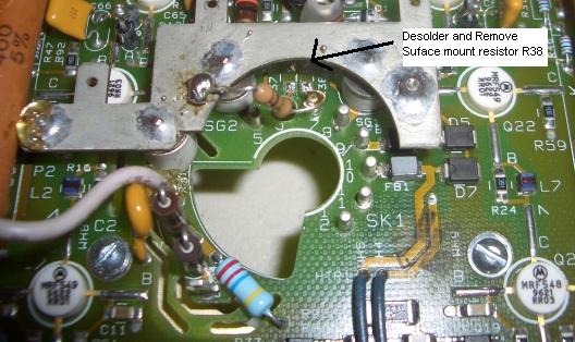
As promised here pics of how to modify Marquee neck cars to work with P19LCP07's, PT-22's and LUG's.
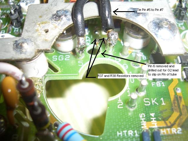
The first pic shows a modified neck card for P19LCP07's and PT-22. Desolder and remove pin 6. Then drill out the hole so that the G2 lead will fit through with no problem onto the pin from the tube that will now protrude through the hole. Use porgressivley larger bit until you get to the size that is large enough. Then desolder the resistor R37 for added insurance.(This procedure is coursey of CMJohnson)
Pics two and three show the next step required to use a LUG in the Marquee. Desolder and remove resistor R38. Using a 1M 1/2W carbon resistor jumper from Pin 7 to the ground block as shown. You will have to scratch up the surface of the ground block to get solder to stick. I put part of the resitor through the hole that is there already. Solder the other end to the tip of pin7. Becareful not to get it too hot or you will desolder the pin from the board. The two things you need to keep in mind is:
1)Position the resistor so that you can still get the G2 lead onto pin 6 but so that it doesnt interfere with the tube center.
2)Make the lead from the resistor to the pin short enough that in can not be pushed over to ground block or it will take the resistor out of the circuit and in essence wil be a straight ground.
EDIT:See updated post below with an additonal way to mod for LUG with more details
| Description: |
|
| Filesize: |
65.09 KB |
| Viewed: |
18404 Time(s) |

|
| Description: |
|
| Filesize: |
65.46 KB |
| Viewed: |
18404 Time(s) |

|
| Description: |
|
| Filesize: |
75.5 KB |
| Viewed: |
18404 Time(s) |
|
_________________
EJ
Last edited by erikjohn on Tue Dec 19, 2006 3:45 pm; edited 2 times in total
|
|
| Back to top |
|
|
Mad Mr H

Joined: 07 Mar 2006
Posts: 641
Location: London , England
|
| Posted: Fri Dec 15, 2006 9:48 am Post subject: |
|
|
I will post this on the UK site,
Many thanks for the info, and your time to do this for others.
Andy.
|
|
| Back to top |
|
|
erikjohn
Joined: 08 Mar 2006
Posts: 636
Location: Florida
|
| Posted: Fri Dec 15, 2006 2:32 pm Post subject: |
|
|
Andy,
I still have one issue and I am not sure what is causing it. I am getting some blooming at higher contrast settings. I have been taliking with Greg Eismann and he has spoke with VDC quite a bit about the swap. I am going to tie the G1 with the KH as he has had alot of success with that as well. He says that in essence this makes the LUG act like a PT-22. I just have to find out if I need to change back the resistor that I installed to the factory value.
_________________
EJ
|
|
| Back to top |
|
|
erikjohn
Joined: 08 Mar 2006
Posts: 636
Location: Florida
|
| Posted: Tue Dec 19, 2006 3:57 pm Post subject: |
|
|
The attached pic shows an alternate way to mod the neck card for the LUG to work in the Marquee. It requires that you do everything same as previous LUG mod I posted with the exception of installing the resistor. In lieu of the resitor from Pin 7(KH) to ground you tie Pin 5(G1) to Pin 7(KH). I am told that internally this makes the tube equivalent to a PT-22.
Initially I can not tell awhole lot of difference between both ways ie with the added resistor or tieing the pins together. I did adjust G2 a bit but not much.
In general the notable thing I am noticing with the LUG is that G2 levels and Drive are significantly lower than with the P19's or PT-22's. Also the way the tube reacts to Contrast and Brightness adjustements is not linear with the the P19's or PT-22's. What I mean by this is that increasing contrast by say 3, more adversely affects the LUG and it seems to be somewhat exponential due the rapid increase I see in blooming.
Thus when you setup grey scale at your 50/50 Contrast/Brighness and then if you turn them up once you are done calibrating you do not get a lineal color balance. This makes setting up things a bit more difficult and I have't yet fooled around alot with it, but I will. This is one reason why it may not be advisable to mix and match LUGS with other tubes.
I will report back once I gather more data.
| Description: |
|
| Filesize: |
87.04 KB |
| Viewed: |
18281 Time(s) |
|
_________________
EJ
Last edited by erikjohn on Tue Dec 19, 2006 4:01 pm; edited 1 time in total
|
|
| Back to top |
|
|
erikjohn
Joined: 08 Mar 2006
Posts: 636
Location: Florida
|
| Posted: Tue Dec 19, 2006 3:58 pm Post subject: |
|
|
Double Post
_________________
EJ
|
|
| Back to top |
|
|
madpoet
Joined: 30 Mar 2006
Posts: 851
|
| Posted: Mon Apr 30, 2007 1:10 pm Post subject: |
|
|
Digging this oldie but goodie up again... was there any agreement on a final method? Tieing 5 and 7 seems easier to me, but I want to make sure whatever I do is the right thing. Got those new LUGs coming from Terry!
_________________
9500LC + MP Mods V2 + HD10F lenses + Frankenyoke V2 = Something nice... I hope I get to actually watch it sometime!
|
|
| Back to top |
|
|
erikjohn
Joined: 08 Mar 2006
Posts: 636
Location: Florida
|
| Posted: Mon Apr 30, 2007 1:31 pm Post subject: |
|
|
Mad,
I have mine setup with the Alt #2 where you tie 5 to 7 and it seems to work fine. I have about 700 hrs on the machine with this mod so it is stable  . .
_________________
EJ
|
|
| Back to top |
|
|
madpoet
Joined: 30 Mar 2006
Posts: 851
|
| Posted: Mon Apr 30, 2007 1:39 pm Post subject: |
|
|
Thanks EJ! Can I ask, what did you use to tie them together? I.e. what kind of wire?
_________________
9500LC + MP Mods V2 + HD10F lenses + Frankenyoke V2 = Something nice... I hope I get to actually watch it sometime!
|
|
| Back to top |
|
|
|
|


