| Author |
Message |
bachiano
Joined: 13 Mar 2006
Posts: 163
|
| Posted: Thu Mar 15, 2012 3:23 pm Post subject: G70 Green Geometry |
|
|
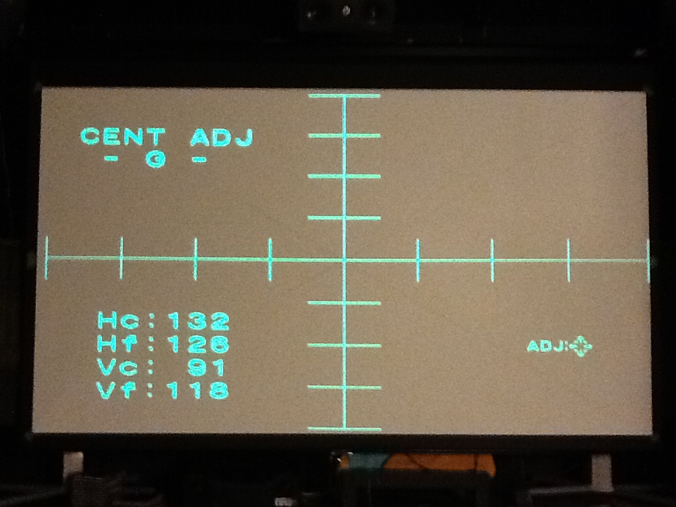
Got my 92" screen and I'm doing another complete setup again - redoing P2.
I just noticed that when projecting a crosshatch pattern with Green.
the left most rectangle is 14 cm
and the most right rectangle is 15 cm.
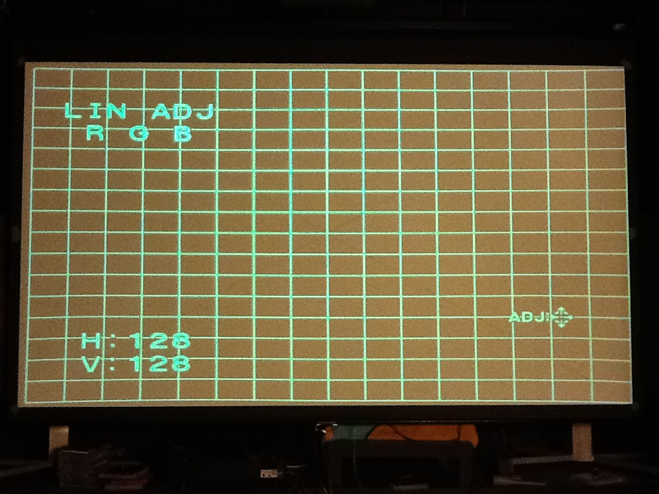
Lin is at 128.
Do I solve this by using Lin or is there another method that allows me to keep Lin at 128?
I did notice that if I use cent and move green to the left that the problem is alleviated.
I have the PJ square to the screen as far as I can tell.
and the green pattern is centered on the tube face.
The center of the crosshatch is centered on the screen.
--------------------------
Another issue is the curves on the upper and lower right corner.
Pin and Pin Bal are not enough to take care of it.
I did notice that if I use cent and move green to the left that the problem is alleviated here as well.
----------------------------
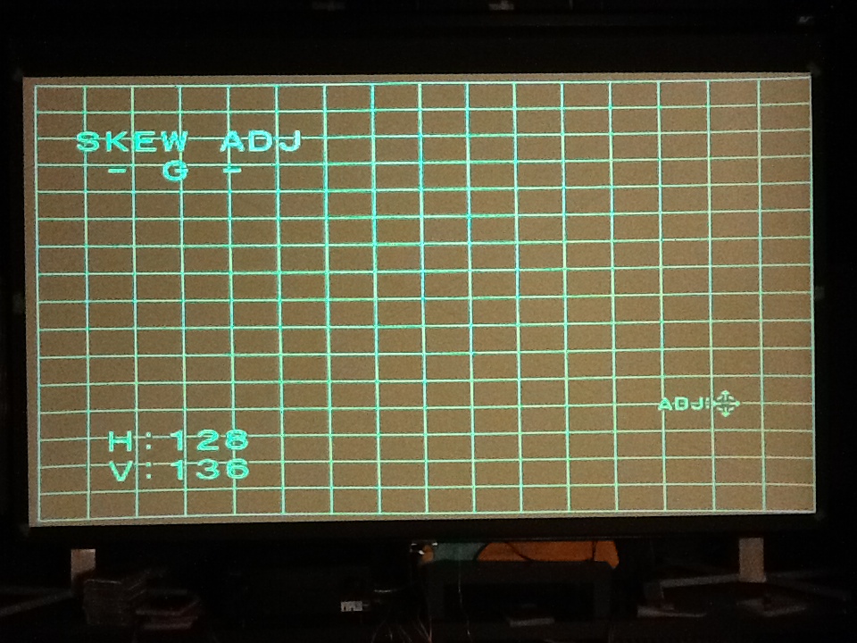
Scheimpflug is done on the green H and V.
DY angle adjustment and MG Focus Coil Angle adjustment are done.
Have not done 2/4 - Pole MG adjustment (center adjustment ) yet. was hoping I could skip that one.
--------------
Thanks
| Description: |
|
| Filesize: |
215.3 KB |
| Viewed: |
1431 Time(s) |
|
| Description: |
|
| Filesize: |
289.88 KB |
| Viewed: |
1431 Time(s) |
|
| Description: |
|
| Filesize: |
288.28 KB |
| Viewed: |
1431 Time(s) |
|
|
|
| Back to top |
|
 |
Curt Palme
CRT Tech
Joined: 08 Mar 2006
Posts: 24396
Location: Langley, BC
TV/Projector: All of them!
|
| Posted: Thu Mar 15, 2012 3:28 pm Post subject: |
|
|
|
First, make sure that all your zone controls are set to 128. Things like the lin controls are never set to 128 when you get perfect convergence/geometry, so sure, tweak the lin control.. ONce you get the geometry as close to perfect as possible, THEN only use the zone adjustments to tweak everything to perfection.
|
|
| Back to top |
|
|
CIR Engineering

Joined: 25 Aug 2008
Posts: 4269
Location: Chicago USA & Berlin Germany
|
| Posted: Thu Mar 15, 2012 8:43 pm Post subject: |
|
|
Is this a 1080p 60Hz setup? If so, the G70 will be at the limit without a video processor to tweak timings.
You need to make sure that your image is in a usable part of the raster, NOT in the middle of the raster. Most likely on a G70 with standard 1080p 60Hz you will need to shift the image left of center inside the raster. The right side of the raster will be compressed and if your image falls inside of the compressed area you will see what you are seeing in the shorter rectangles on the right side of the screen (front projection). You may however not have enough raster to work with really so there may be a trade off.
Having some bend at the top is normal on a G70 with standard 1080p 60Hz timings as well.
With a VP you can add some lines to the H and V to add blanking. On the H you could run something like 2300 total lines and on the V you could run 1160 or so. This would get rid of the bend and compression if that is what you are seeing.
craigr
_________________
JETI 1501-HiRes 2nm Spectroradiometer
JETI 1211 Spectroradiometer
Photo Research PR-650 Spectroradiometer
Klein K10-A Colorimeter
Murideo Fresco SIX-G HDMI 2.x Multimedia Generator
Murideo Fresco SIX-A HDMI 2.x Analyzer
Light Illusion ColourSpace XPT Color Calibration Software
Light Illusion LightSpace XPT Pro Version 10.x Color Calibration Software
OMARDRIS JVC Software Patch to use K10-A and Jeti with JVC OEM AutoCal Software!
Sencore CR7000 CRT Tube Analyzer / Rejuvenater
Authorized Dealer for Lumagen & just about everything worth buying 
www.CIR-Engineering.com - craigr@cir-engineering.com
Phone: 865-405-6892
|
|
| Back to top |
|
|
|
|


