|
As this forum is rarely used anymore, we've locked it. Feel free to browse and read. Questions? Please reach out to us directly. Cheers! |

|
 |
|
|
| Author |
Message |
CIR Engineering

Joined: 25 Aug 2008
Posts: 4269
Location: Chicago USA & Berlin Germany
|
| Posted: Tue Feb 28, 2012 4:20 pm Post subject: |
|
|
Generally you want the gap between the edge of the image and the edged of the tube to be between 5~8mm. I personally usually make it more lik3 3~5mm on my own machines. It doesn't have to be perfect, but the closer you get it to even, the better. The advantage to this system is that it is pretty easy to tell 5~8mm by eye because it is such a small distance that it is easy to see. Determining the center of the tube (traditional method) is really a lot harder to spot by eye.
If all this is too confusing, just do your setup by referencing the center as you were going to. The way you were going to do the setup is the traditional way as described in the manual. The edge weighted method is just better for those who want to squeeze out every last bit of performance, and is a noticeable improvement. The edge weighted system is also easier to perform once you understand it.
When you do the setup based on the edges of the tube, you can make your image square to the edges of the tube to start. Of course, when you match the image to the screen, you will need to use some keystone and the image will become something close to an isosceles trapezoid on the tube face (16x9 on screen). At that point, you want to be sure that the two corners of the trapezoid closest to the tube edge are around 5mm from the edge.
Just start playing, you'll see.
craigr
_________________
JETI 1501-HiRes 2nm Spectroradiometer
JETI 1211 Spectroradiometer
Photo Research PR-650 Spectroradiometer
Klein K10-A Colorimeter
Murideo Fresco SIX-G HDMI 2.x Multimedia Generator
Murideo Fresco SIX-A HDMI 2.x Analyzer
Light Illusion ColourSpace XPT Color Calibration Software
Light Illusion LightSpace XPT Pro Version 10.x Color Calibration Software
OMARDRIS JVC Software Patch to use K10-A and Jeti with JVC OEM AutoCal Software!
Sencore CR7000 CRT Tube Analyzer / Rejuvenater
Authorized Dealer for Lumagen & just about everything worth buying 
www.CIR-Engineering.com - craigr@cir-engineering.com
Phone: 865-405-6892
|
|
| Back to top |
|
 |
bachiano
Joined: 13 Mar 2006
Posts: 163
|
| Posted: Tue Feb 28, 2012 9:47 pm Post subject: |
|
|
Hi Craigr
Been playing all day 
I've returned all to 128 using P2.
Took the lenses off.
Maxed out both V and H .
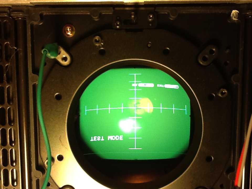
Below are pics of the Crosshair and Crosshatch pattern.
After I took the lenses off and was trying to center the Crosshatch on the green I noticed four little tabs.
I hope you can see the little tabs @ 12, 3, 6 and 9 o'clock.
Can I presume these tabs indicate the true V and H center of the CRT ?
1) If true, then when I center the Crosshatch on the tube face I will no longer be at 128 H - Is that ok?
2) in the Crosshair it is obvious that the H is too far north, in relation to the tabs @ 9 and 3 o'clock, even at 128.
It is also obvious on the top and bottom cross in relation to the tube's edge.
Although it is hard to see from the pic, the H is also a little skewed in relation to the tabs @ 9 and 3 o'clock.
- originally I did the DY angle adjustment on the blue and Red to match the Greens H.
But now I think I need to true up the green's H to the tabs @ 9 and 3 o'clock and redo R and B.
3) If that makes sense, then after that, I will center the crosshatch of all the tubes
and then rotate the R and B to match the periphery of the Green crosshatch.
I'm probably over thinking this but I'd rather get it right, right now, before my wife says "enough is enough"
Thanks for all your help !
Greatly appreciated !!!
P.S. I definitely want to "squeeze out every last bit of performance" as this PJ is practically new
and I want to eventually play with 1080p.
Right now, with my setup, 1080p is definitely not possible.
| Description: |
|
| Filesize: |
228.72 KB |
| Viewed: |
1746 Time(s) |
|
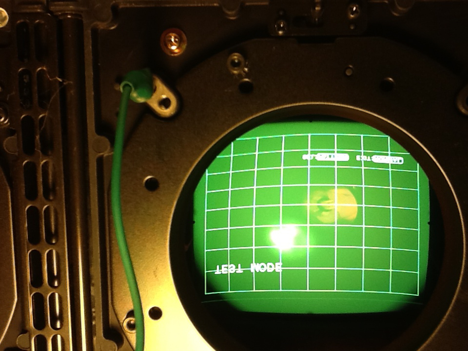
| Description: |
|
| Filesize: |
241.17 KB |
| Viewed: |
1746 Time(s) |
|
|
|
| Back to top |
|
|
AFryia
Joined: 09 Mar 2006
Posts: 965
Location: S.E. Michigan VPH-G70Q
|
| Posted: Tue Feb 28, 2012 11:49 pm Post subject: |
|
|
| bachiano wrote: |
Can I presume these tabs indicate the true V and H center of the CRT ?
|
No I don't think so. They may be close but it varies. It depends how the tubes were fit to the 'C' element.
Use the edge method to find true center.
|
|
| Back to top |
|
|
bachiano
Joined: 13 Mar 2006
Posts: 163
|
| Posted: Wed Feb 29, 2012 12:07 am Post subject: |
|
|
Hi Afryia.
I did a little more work this afternoon using the edge method and indeed the tabs are close but not perfectly centered.
The H skew on the green however, is a little off, I think.
It's a little lower on the left than on the right?
What do you think?
Can you see it in the pics?
I'm getting close
Thanks
|
|
| Back to top |
|
|
CIR Engineering
Joined: 25 Aug 2008
Posts: 4269
Location: Chicago USA & Berlin Germany
|
| Posted: Wed Feb 29, 2012 12:25 am Post subject: |
|
|
| bachiano wrote: |
After I took the lenses off and was trying to center the Crosshatch on the green I noticed four little tabs.
I hope you can see the little tabs @ 12, 3, 6 and 9 o'clock.
Can I presume these tabs indicate the true V and H center of the CRT ? |
Yes, those are center.
| bachiano wrote: |
1) If true, then when I center the Crosshatch on the tube face I will no longer be at 128 H - Is that ok? |
Yes, that is normal on a G70.
| bachiano wrote: |
Although it is hard to see from the pic, the H is also a little skewed in relation to the tabs @ 9 and 3 o'clock.
- originally I did the DY angle adjustment on the blue and Red to match the Greens H.
But now I think I need to true up the green's H to the tabs @ 9 and 3 o'clock and redo R and B. |
Since you know how to do DY coil adjustment that is what you should do. I like to zero out EVERYTHING when I do DY coils. This includes zone, pincushion, keystone, and especially skew.
Hit the screen with a laser level and then rotate the DY coil on green to match the laser. Then rotate red and blue to match green. Don't worry about vertical, just concentrate on horizontal.
The projector case will obviously have to be open while you rotate the DY. So be sure to close the case after green and make sure it is still on the level. This is double true for the blue and red DYs.
| bachiano wrote: |
3) If that makes sense, then after that, I will center the crosshatch of all the tubes
and then rotate the R and B to match the periphery of the Green crosshatch. |
Yes, if you want to use the center weighted technique. As I explained, you will get better performance if you use the left and right side edges of the image instead of the center.
| bachiano wrote: |
I'm probably over thinking this but I'd rather get it right, right now, before my wife says "enough is enough" |
You're not over thinking this. It's complicated the first time you do it and getting it correct has a huge impact on the final image quality.
| bachiano wrote: |
P.S. I definitely want to "squeeze out every last bit of performance" as this PJ is practically new
and I want to eventually play with 1080p. Right now, with my setup, 1080p is definitely not possible. |
Than use the side weighted technique! 1080p should look very good on an optimized G70.
craigr
_________________
JETI 1501-HiRes 2nm Spectroradiometer
JETI 1211 Spectroradiometer
Photo Research PR-650 Spectroradiometer
Klein K10-A Colorimeter
Murideo Fresco SIX-G HDMI 2.x Multimedia Generator
Murideo Fresco SIX-A HDMI 2.x Analyzer
Light Illusion ColourSpace XPT Color Calibration Software
Light Illusion LightSpace XPT Pro Version 10.x Color Calibration Software
OMARDRIS JVC Software Patch to use K10-A and Jeti with JVC OEM AutoCal Software!
Sencore CR7000 CRT Tube Analyzer / Rejuvenater
Authorized Dealer for Lumagen & just about everything worth buying
www.CIR-Engineering.com - craigr@cir-engineering.com
Phone: 865-405-6892
Last edited by CIR Engineering on Wed Feb 29, 2012 12:32 am; edited 1 time in total
|
|
| Back to top |
|
|
|
|
|
|
|
You cannot post new topics in this forum
You cannot reply to topics in this forum
You cannot edit your posts in this forum
You cannot delete your posts in this forum
You cannot vote in polls in this forum
You cannot attach files in this forum
You can download files in this forum
|
Forum powered by phpBB © phpBB Group
|
|


