|
As this forum is rarely used anymore, we've locked it. Feel free to browse and read. Questions? Please reach out to us directly. Cheers! |

|
 |
|
|
| Author |
Message |
Curt Palme
CRT Tech
Joined: 08 Mar 2006
Posts: 24396
Location: Langley, BC
TV/Projector: All of them!
|
| Posted: Tue Jan 24, 2012 1:16 am Post subject: Anyone got a NEC PG/Runco 900 chassis? Experiment time! |
|
|
OK, who says I can't learn new stuff in the CRT projector world?
One of the most puzzling boards to repair is the NEC system boards. I've swapped tips with a few guys over the years, but even Doug Baisey was usually stumped with them. Anyone with an NEC knows about the scrambled menus, bad menus, no sync and no pix conditions, all caused by a bad system board.
What I have here are two system boards that I've managed to get rid of the scrambled menus, and the sync on all resolutions is now solid. But.. what I've found is that the memory dies when I unplug the power cord from the set. When the power is kept applied to the set but you power down, the memory stays intact. This is a PITA though, as it means that after every power outage, the projector needs a ground up setup.
Or does it? 
here's what I've been doing, and I need someone with a good working NEC PG (perferably not someone's main viewing set) to try:
Again, as most of you NEC owners know, once you unplug the power cord from any NEC, the back panel will remain lit while the standby power supply capacitors discharge. The back panel stays lit for say 30 seconds or so, maybe 20. To save time while I'm pulling system boards in and out of the card cage, what I've been doing for years is to shut the set down via the remote, then I pull the power cord or turn off the main power switch on the LVPS, so that the back panel stays lit.
THEN, I power the set back up again via the remote or back pushbutton, and the set will power up momentarily, from the juice stored in the LVPS. What I found out by accident today is both with the test chassis system board and the partially repaired customer system board that I was working on, the set will NOT retain its memory if I power the shut down set back up. That seems to trigger a memory dump. IF however, I power down normally, pull the AC plug, and let the set sit, then plug AC power back in, the set retains its memory.
What I need someone here with a working NEC PG to do is to see if the system board loses its memory if you try to power the set up for a second once the set is unplugged. If it dumps its memory, then that's normal, and these two system boards are repaired. If it retains the memory, then there's still a problem on these two boards..
Thanks in advance, and if the above isn't clear, please let me know.
|
|
| Back to top |
|
 |
CasetheCorvetteman

Joined: 09 Nov 2008
Posts: 6326
Location: Australia
|
| Posted: Tue Jan 24, 2012 6:42 am Post subject: |
|
|
No Curt, cause ive done this with mine since the day dot, and all 3 of my system boards here that work still retain their memory when i do this.
I have always turned off the main switch, then pressed the power on button on the remote to discharge it quicker, and never ever lost any memory.
Ive done it hundreds of times.
|
|
| Back to top |
|
|
Curt Palme
CRT Tech
Joined: 08 Mar 2006
Posts: 24396
Location: Langley, BC
TV/Projector: All of them!
|
| Posted: Tue Jan 24, 2012 2:58 pm Post subject: |
|
|
OK, thanks, you're right. Came downstairs this morning, and the memory is wiped.  I'll have to tell the customer to put a small UPS on the NEC.. I'll have to tell the customer to put a small UPS on the NEC..
|
|
| Back to top |
|
|
macgyver655
Joined: 22 Aug 2007
Posts: 8508
|
| Posted: Tue Jan 24, 2012 3:09 pm Post subject: |
|
|
|
I'm curious, are you entries completely gone or are they there and it wont lock onto them? Or it locks onto the entry but all the settings in that entry are gone?
|
|
| Back to top |
|
|
Curt Palme
CRT Tech
Joined: 08 Mar 2006
Posts: 24396
Location: Langley, BC
TV/Projector: All of them!
|
| Posted: Tue Jan 24, 2012 6:17 pm Post subject: |
|
|
Entries are all there, but the system board won't select them. If I manually select the memory from last night (720p), I stilll get an 'incompatible signal' error message.
I'm going to change the supercap on both boards, Ive got some spares here.
|
|
| Back to top |
|
|
macgyver655
Joined: 22 Aug 2007
Posts: 8508
|
| Posted: Tue Jan 24, 2012 6:52 pm Post subject: |
|
|
|
Try those same adjustments I emailed you on these. I've been on this road before also.
|
|
| Back to top |
|
|
Curt Palme
CRT Tech
Joined: 08 Mar 2006
Posts: 24396
Location: Langley, BC
TV/Projector: All of them!
|
| Posted: Tue Jan 24, 2012 7:10 pm Post subject: |
|
|
Will do. I'm going to send the customer's board back. I noticed that the supercap on the board dropped to well under 5 volts (but over 4) when unplugged overnight. Someone posted long ago that this cap only kept the time and date accurate, do you know if it affects memory as well?
I'm discounting the repair, and am telling the customer to get a cheap UPS to put on top of the NEC, so that the standby supply will keep working if he has a power outage. I know Tinman has a bunch of NEC PGs at his place that I'll grab if I drive to LA in Feb. In the meantime I'll play with the remaining 2 or 3 system boards I have here.
|
|
| Back to top |
|
|
macgyver655
Joined: 22 Aug 2007
Posts: 8508
|
| Posted: Tue Jan 24, 2012 7:25 pm Post subject: |
|
|
|
According to the print that cap is only tied to the date/clock ic (ic8222) and it only requires 3.6v to maintain it's memory.
|
|
| Back to top |
|
|
Jeremy112

Joined: 28 Sep 2006
Posts: 2649
Location: Fond du Lac, WI
|
| Posted: Tue Jan 24, 2012 9:25 pm Post subject: |
|
|
Never had this happen on either of my NEC PG sets curt, they are rock solid (save for the bad PSU in my PG Plain) unfortunately (for you).
Hope this doesnt happen to me!!
_________________
When I'm asking for a Model number, that doesn't mean I'm asking for a nude photo with your number on it 
|
|
| Back to top |
|
|
CasetheCorvetteman
Joined: 09 Nov 2008
Posts: 6326
Location: Australia
|
| Posted: Wed Jan 25, 2012 6:17 am Post subject: |
|
|
Curt ive had the big capacitor off the board for over 30 minutes on another system board and also didnt lose my memories on it, so im not sure exactly how it does retain those memories or where, and how hard it would be to swap them out of a dead board and into a good one.
Also, careful with those words "cheap UPS", if its not big enough to supply the set in the event of power failure while its running, ive never put the ammeter over the power cord on it but i wouldnt like to see anything less than a 700 VA supply on it ( id be aiming for 1,200 VA myself just to be sure ), or youll run the risk of cooking the UPS as well as losing your memory!!
Not sure what the US spec PG says on the back, but mine gives no VA or wattage rating, only a current rating, only max current, 4.4A x 230v = 1012 VA.... Would have to be peak... No idea what sort of power factor it runs at either, so assume its lagging...
|
|
| Back to top |
|
|
gjaky

Joined: 05 Jun 2010
Posts: 2802
Location: Budapest, Hungary
|
| Posted: Wed Jan 25, 2012 7:42 am Post subject: |
|
|
| CasetheCorvetteman wrote: | Curt ive had the big capacitor off the board for over 30 minutes on another system board and also didnt lose my memories on it, so im not sure exactly how it does retain those memories or where, and how hard it would be to swap them out of a dead board and into a good one.
Also, careful with those words "cheap UPS", if its not big enough to supply the set in the event of power failure while its running, ive never put the ammeter over the power cord on it but i wouldnt like to see anything less than a 700 VA supply on it ( id be aiming for 1,200 VA myself just to be sure ), or youll run the risk of cooking the UPS as well as losing your memory!!
Not sure what the US spec PG says on the back, but mine gives no VA or wattage rating, only a current rating, only max current, 4.4A x 230v = 1012 VA.... Would have to be peak... No idea what sort of power factor it runs at either, so assume its lagging... |
Once I've measured the current of my PG xtra, it was about 1,5A on 230V mains, but I think Curt only wants to save the memory in that case if the set is in standby but there is a power failure. In standby my xtra ate 40W, thats that's why I always shut down with the mains switch. Once or twice it happened to me that I didn't switch on the pj for some weeks then the clock settings were gone, but my setup settings worked just fine.
_________________
projectors in the past : NEC 6-9PG xtra, Electrohome Marquee 6-7500, NEC XG 1351 LC ( with super modified Electrohome VNB neckboard !!!)
current: VDC Marquee 9500LC
The MOD: VNB-DB, VIM-DB
|
|
| Back to top |
|
|
barclay66

Joined: 27 Jun 2011
Posts: 1304
Location: Germany
TV/Projector: Marquee 9500 Ultra
|
| Posted: Wed Jan 25, 2012 8:52 am Post subject: |
|
|
Hi,
If anyone could tell me where to find the schematic for the System Board (and/or other CPU Boards in the NEC PG) I could have a look at it and possibly could find out where the settings are stored and which IC is the possible culprit. I could imagine that although the memory IC itself is fine it might screw up its content in specific PowerUp/PowerDown situations. Maybe a small modification (VCC buffering/decoupling) could avoid this. Impossible to know without the schematics of course...
Regards,
barclay66
|
|
| Back to top |
|
|
CasetheCorvetteman
Joined: 09 Nov 2008
Posts: 6326
Location: Australia
|
| Posted: Wed Jan 25, 2012 1:58 pm Post subject: |
|
|
| gjaky wrote: |
Once I've measured the current of my PG xtra, it was about 1,5A on 230V mains, but I think Curt only wants to save the memory in that case if the set is in standby but there is a power failure. In standby my xtra ate 40W, thats that's why I always shut down with the mains switch. Once or twice it happened to me that I didn't switch on the pj for some weeks then the clock settings were gone, but my setup settings worked just fine. |
I know what he wants to do, however what happens if the set is on in full flight and the power goes out?? Then he loses the lot including the UPS cause he or someone else has it grossly over loaded. By your figures ( which sound alot more reasonable than the 4.4A on the back ) 500 VA will do it no worries, and it might, but if it pulls more than the UPS can supply itll go way under voltage, which could cause issues too.
How did you measure the standby to be 40 watts?? If you measured the current drawn while in standby and used P=VxI, that is 40 VA, or did you use a watt-hour meter to measure apparent power? Is your power consumption there charged in kWh or kVAh?
P.S. Has anyone ever looked at the AC wave form coming out of a cheap UPS? 
|
|
| Back to top |
|
|
gjaky
Joined: 05 Jun 2010
Posts: 2802
Location: Budapest, Hungary
|
| Posted: Wed Jan 25, 2012 2:20 pm Post subject: |
|
|
Nothing special, just measured the current draw so it was 40VA, to be accurate, you are right. Although we pay after the kWh usage.
_________________
projectors in the past : NEC 6-9PG xtra, Electrohome Marquee 6-7500, NEC XG 1351 LC ( with super modified Electrohome VNB neckboard !!!)
current: VDC Marquee 9500LC
The MOD: VNB-DB, VIM-DB
|
|
| Back to top |
|
|
CasetheCorvetteman
Joined: 09 Nov 2008
Posts: 6326
Location: Australia
|
| Posted: Wed Jan 25, 2012 2:38 pm Post subject: |
|
|
Without knowing the phase angle or using a watt-hour meter that shows instant power consumption, there is no way to know the apparent power consumption. Could be close to 40 watts, but it could be 5 watts for all we really know without measuring it with the correct equipment ( could be anything really, but at least we know the maximum itll be!! ).
I remember going through all this not long ago when someone put it to me that an SELV lighting transformer was using 17 watts without a lamp even connected to it, when i looked into it further, it was a wire wound transformer with no power factor correction, and with no load, it was basically just an inductor, and 17 watts was 17 VA. Connecting a 50 watt lamp showed a consumption of 53 VA.... With a watt-hour meter it was under half a watt with no lamp....
|
|
| Back to top |
|
|
CasetheCorvetteman
Joined: 09 Nov 2008
Posts: 6326
Location: Australia
|
| Posted: Wed Jan 25, 2012 2:54 pm Post subject: |
|
|
| gjaky wrote: | | Although we pay after the kWh usage. |
Sorry mate i missed that bit, and i figured you would, it is only large energy consumers ( as in non domestic ) here that pay different rates based on power factor, and there was talk of them being charged in kVAh instead of kWh.
The world could save a hell of alot of energy if power factor correction was used in more places.
|
|
| Back to top |
|
|
gjaky
Joined: 05 Jun 2010
Posts: 2802
Location: Budapest, Hungary
|
| Posted: Wed Jan 25, 2012 2:55 pm Post subject: |
|
|
By the look of the LVPS schematics of my PG xtra it has active PFC, however looking at plain PG's schematics it doesn't have. this is Funny because the creepy old GP5000 also had active PFC.
_________________
projectors in the past : NEC 6-9PG xtra, Electrohome Marquee 6-7500, NEC XG 1351 LC ( with super modified Electrohome VNB neckboard !!!)
current: VDC Marquee 9500LC
The MOD: VNB-DB, VIM-DB
|
|
| Back to top |
|
|
barclay66
Joined: 27 Jun 2011
Posts: 1304
Location: Germany
TV/Projector: Marquee 9500 Ultra
|
| Posted: Wed Jan 25, 2012 3:54 pm Post subject: |
|
|
Hi,
I just hope this doesn't get too long...
Thanks to gjaky I was able to take a look into the schematics and made my personal analysis of the problem. The following is based on my experience with digital circuits only and none of the solutions presented has been verified yet (I just don't have a NEC PG to test with)! I might be thinking wrong in any area and if so I'd like to participate in any further advanced knowledge anyone has.
1.) Who's the culprit?
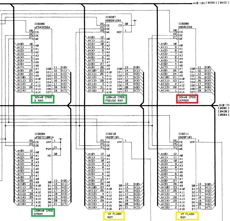
When You look at the system board's schematic You might see that there's a main CPU (IC8201, µPD70325L), a slave CPU (IC8232, µPD50H), lots of memory devices and lots of interface circuitry. What we have to look at is the memory bank of the main CPU. Below is an edited excerpt of the schematic showing it:

NEC combined different types of memory devices according to functional and possibly budgetary requirements:
- One Static RAM, one Pseudo Static RAM and an EPROM (marked in green)
- Two Flash ROMs (marked in yellow)
- One EEPROM (marked in red)
I don't think that the RAMs or the EPROM can cause the symtoms as the are designed to loose memory at Power Off (RAM) or will retain it any circumstance (EPROM). Corrupt data in the latter would be a permanant problem. Further I don't think that the Flash ROMs can be held liable as those seem to be the location of the firmware and are only reprogrammed using an external connection. To me the most likely device containing the settings is the EEPROM!
2.) What's happening with it?
It seems as if the short Power Up sequence (fed only by the capacitors of the Power Supply) triggers an event in which the data of the EEPROM becomes corrupt. Is this possible? --> YES!!!
I dug up the data sheet for it and on page 18 it clearly states:
When VCC is turned on or off, noise on the control pins generated by external circuits (CPU, etc) may act as a trigger and turn the EEPROM to program mode by mistake. To prevent this unintentional programming, the EEPROM must be kept in an unprogrammable state while the CPU is in an unstable state.
Another potential source of the problem could be noise during Power Up and Power down. On page 17 of the data sheet You can read this:
During readout or standby, noise on the control pins may act as a trigger and turn the EEPROM to programming mode by mistake. To prevent this phenomenon, this device has a noise cancelation function that cuts noise if its width is 20 ns
or less. Be careful not to allow noise of a width of more than 20 ns on the control pins.
It could be possible that specific batches of EEPROMs are more vulnerable to the effect than others. It too could be related to their age and/or number of Write cycles. This would explain why it doesn't happen on all machines.
3.) What can be done
I've thought about this for some time and have come up with four different solutions:
a.) Buffering Vcc of the EEPROM
If the supply voltage of the EEPROM is too noisy this noise could trigger one of the effects described above. I'd recommend adding a low ESR capacitor (electrolytic or tantalium) with 10-100µF/10V across the supply pins of the EEPROM. If the EEPROM is in a DIP casing those would be Pin 14 (-) and Pin 28 (+). If it is in a TSOP casing those would be Pin 21 (-) and Pin 7 (+).
b.) Enlarging the Power-On-Reset Pulse
First a picture of the schematic section:

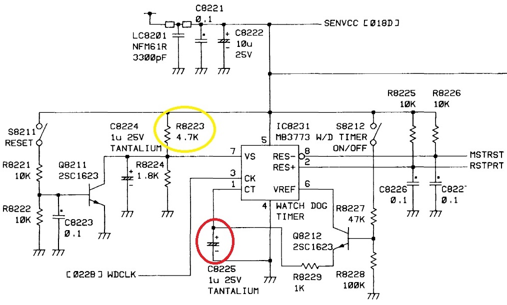
If the CPU starts messing around with address and data lines before the EEPROM is ready this could result in corrupted data too. The CPU won't start any activity as long as its Reset line is active (low). The system board has a special circuit for a defined Power-On-Reset (IC8231, MB3773). According to its data sheet the duration of the pulse is determined by the capacitor connected to its pin 1 (C8225, 1µF tantalium). Increasing its value will enlarge it and will therefore keep the CPU on hold for a longer time (linear increase). I'd try other values up to 2.2µF if available using the same type of capacitor.
c.) Raising the Power-Good trigger level
The same device (IC8231, MB3773) also does supply voltage monitoring. It will keep the Reset lines active as long as the supply voltage hasn't reached a specific level. According to the data sheet this level is determined by the voltage on pin 7 and this level is set with two resistors (R8223, 4K7 and R8224, 1K8). With the current resistors this level should be somewhere around 4.3V. For the fault scenario this might be too low. I'd try replacing R8223 with an 1% 5K6 resistor. This should lift the trigger level to about 4.5V and might be safer. Caution: Higher values for R8223 could raise the level above normal supply voltage! The CPU would be held in Reset forever!!!
d.) Enabling Data Protection on the EEPROM
Right now it's only the CPU managing the control lines of the EEPROM. If the CPU is operating in an undefined state those lines may be fluctuating uncontrollaby too. Gladly, the EEPROM designers have forseen this! Another look at the data sheet reveals a Data Protection mechanism on page 18:
The EEPROM should be kept in unprogrammable state during VCC on/off by using CPU RESET signal.
To realize the unprogrammable state, the input level of control pins must be held as shown in the table below:
-> The table shows that either CE or WE should be high or OE should be low
My idea consists in rerouting the Reset signal so that the Data Protection stays active as long as the CPU receives a Reset signal. Please see my modification in the picture below:

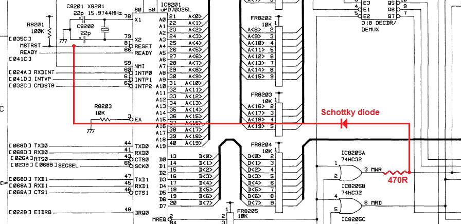
The Reset signal is taken from the CPU's input (this is coming from IC8231, MB3773) and is connected to the output of IC8205A (74HC32, quad OR gate) via a diode that should have a low voltage drop; therefore I would recommend using a schottky diode or something similar. The diode seems to be reversed because we're dealing with an inverted logic: Draning away the voltage makes the line active. The diode is a must because otherwise any activation of the OE line by the CPU would trigger a reset. In order to protect IC8205A's output from being damaged it has to be buffered with an additional resistor (470ohm). So even if IC8205A's output is high (5V) the OE line can be pulled low (0V) by IC8231 without damaging either circuit's output. It could be possible that the resistor's value is too high. I wouldn't go below 250ohm because the current flow would raise above 20mA which is the current limit of both devices.
In my point of view option b.) and d.) have the largest potential. If anyone doesn't find the datasheets of the EEPROM and the Reset circuit I can post those too.
Umm, quite long indeed...
Regards,
barclay66
| Description: |
|
| Filesize: |
157.97 KB |
| Viewed: |
7174 Time(s) |
|
| Description: |
|
| Filesize: |
129.26 KB |
| Viewed: |
7174 Time(s) |
|
| Description: |
|
| Filesize: |
214.13 KB |
| Viewed: |
7174 Time(s) |
|
|
|
| Back to top |
|
|
flipdog

Joined: 22 Dec 2011
Posts: 156
|
| Posted: Wed Jan 25, 2012 4:01 pm Post subject: |
|
|
. 
Last edited by flipdog on Wed Jan 25, 2012 4:03 pm; edited 1 time in total
|
|
| Back to top |
|
|
Curt Palme
CRT Tech
Joined: 08 Mar 2006
Posts: 24396
Location: Langley, BC
TV/Projector: All of them!
|
| Posted: Wed Jan 25, 2012 4:02 pm Post subject: |
|
|
Thanks for that! That's the type of info that I'm weak on, having been raised on analog circuits.  I've sent the customer's board back now, but will try a few things with my own system board... once the NEC is back on the bench in a couple of weeks. I've sent the customer's board back now, but will try a few things with my own system board... once the NEC is back on the bench in a couple of weeks.
|
|
| Back to top |
|
|
|
|
|
|
|
You cannot post new topics in this forum
You cannot reply to topics in this forum
You cannot edit your posts in this forum
You cannot delete your posts in this forum
You cannot vote in polls in this forum
You cannot attach files in this forum
You can download files in this forum
|
Forum powered by phpBB © phpBB Group
|
|


