| Author |
Message |
Nashou66

Joined: 12 Jan 2007
Posts: 16171
Location: West Seneca NY
|
| Posted: Tue May 07, 2013 3:55 pm Post subject: |
|
|
| barclay66 wrote: | | Nashou66 wrote: | | The Yellow wire is the 2.5 volt volume reference I assume. |
Exactly. It's the output of the D/A converter.
| Nashou66 wrote: | | And the top of R5 is the VDD correct? |
Nope. VDD (+5V) is at the bottom of R1 (pin 16 of the HC4053). R5 is one of the three 680K resistors (see schematic).
Regards,
barclay66 |
Oops yeah I meant R1 but i still got the wrong end. So the top of R1 and bottom of R2 are connected along with R3 but are they connected to the board at that junction? It looks as iff there is a solder through point under that spot.
Athanasios
_________________
Don't blame your underwear for your crooked ass~ unknown Greek philosopher
"Republicans believe every day is the Fourth of July, but the Democrats believe every day is April 15." --- President Reagan
One Smart Dog!!!
Marquee High Performance Bellows now shipping!!
Marquee Modifications and Performance Enhancement
Marquee C-element and Bellow removal
|
|
| Back to top |
|
 |
barclay66

Joined: 27 Jun 2011
Posts: 1304
Location: Germany
TV/Projector: Marquee 9500 Ultra
|
| Posted: Tue May 07, 2013 4:04 pm Post subject: |
|
|
| Nashou66 wrote: |
Oops yeah I meant R1 but i still got the wrong end. So the top of R1 and bottom of R2 are connected along with R3 but are they connected to the board at that junction? It looks as iff there is a solder through point under that spot. |
The connection between R1/R2/R3 isn't connected to anything else. It isn't touching the board...
|
|
| Back to top |
|
|
Nashou66
Joined: 12 Jan 2007
Posts: 16171
Location: West Seneca NY
|
| Posted: Tue May 07, 2013 4:15 pm Post subject: |
|
|
| barclay66 wrote: | | Nashou66 wrote: |
Oops yeah I meant R1 but i still got the wrong end. So the top of R1 and bottom of R2 are connected along with R3 but are they connected to the board at that junction? It looks as iff there is a solder through point under that spot. |
The connection between R1/R2/R3 isn't connected to anything else. It isn't touching the board... |
Thanks. If I use large resitors I might have to put some isolation under that point.
I will also cut the ground point under the board for pin 12 and then run the 2.5 volt line on the under side, its three very thin pints to the ground, It will keep the top a bit cleaner looking .
A smd resistor from 13 to 14 will also work by cutting the trace to 13 and adding the SMD from pin 13 to the through solder point, Unless I have a 403 size resistor it would fit right between pins. I think all mine are 1206 and 803 size.
Nashou
_________________
Don't blame your underwear for your crooked ass~ unknown Greek philosopher
"Republicans believe every day is the Fourth of July, but the Democrats believe every day is April 15." --- President Reagan
One Smart Dog!!!
Marquee High Performance Bellows now shipping!!
Marquee Modifications and Performance Enhancement
Marquee C-element and Bellow removal
|
|
| Back to top |
|
|
Nashou66
Joined: 12 Jan 2007
Posts: 16171
Location: West Seneca NY
|
| Posted: Fri May 10, 2013 3:49 am Post subject: |
|
|
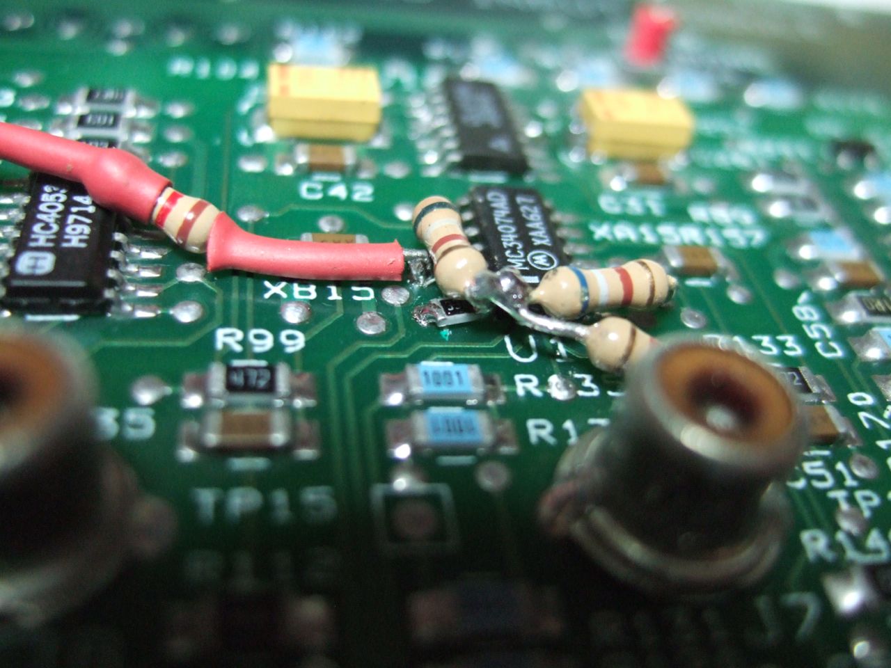
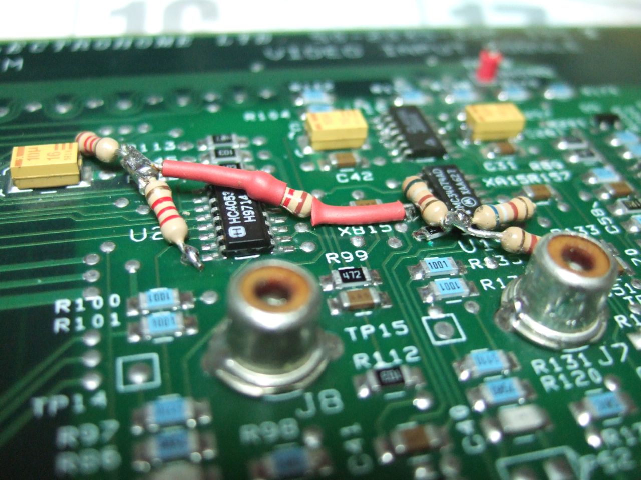
Ok I tried the mod with not exact resistor values. I got the adjustment to work but the line remained and it also would crush the top white IRE patterns on the internal pattern.
So I ask are the values that specific? on the 1.1K the ones I used measured 1.175k and the 680ohm where about 640.
the 2,2 was closer and the 3.3k I used a SMD chip resitor that was perfect value.
| Description: |
|
| Filesize: |
152.15 KB |
| Viewed: |
3148 Time(s) |
|
| Description: |
|
| Filesize: |
178.2 KB |
| Viewed: |
3148 Time(s) |
|
_________________
Don't blame your underwear for your crooked ass~ unknown Greek philosopher
"Republicans believe every day is the Fourth of July, but the Democrats believe every day is April 15." --- President Reagan
One Smart Dog!!!
Marquee High Performance Bellows now shipping!!
Marquee Modifications and Performance Enhancement
Marquee C-element and Bellow removal
|
|
| Back to top |
|
|
barclay66
Joined: 27 Jun 2011
Posts: 1304
Location: Germany
TV/Projector: Marquee 9500 Ultra
|
| Posted: Fri May 10, 2013 5:45 am Post subject: |
|
|
Hi,
R5/R6/R7 are 680K (680 Kiloohms), not 680 ohms.
If the other resistors are off You might get a different adjustment range and/or the neutral setting isnt't at 50% volume as intended.
Regards,
barclay66
|
|
| Back to top |
|
|
Nashou66
Joined: 12 Jan 2007
Posts: 16171
Location: West Seneca NY
|
|
| Back to top |
|
|
Nashou66
Joined: 12 Jan 2007
Posts: 16171
Location: West Seneca NY
|
| Posted: Sat May 11, 2013 2:03 am Post subject: |
|
|
Radio Shack did not have the right value so Digikey to the rescue. I ordered 1% metal film 1/4 waters to do the job right.
I'll still use the 3.3k SMD 805 size. That worked out nice as I just cut the trace of pin 14 and then put the resistor from the pin to the through solder point that pin 13 also goes to.
Lets see how it goes once I get other resistors in in.
Athanasios
_________________
Don't blame your underwear for your crooked ass~ unknown Greek philosopher
"Republicans believe every day is the Fourth of July, but the Democrats believe every day is April 15." --- President Reagan
One Smart Dog!!!
Marquee High Performance Bellows now shipping!!
Marquee Modifications and Performance Enhancement
Marquee C-element and Bellow removal
|
|
| Back to top |
|
|
|
|