| Author |
Message |
tse
Joined: 03 May 2006
Posts: 1014
Location: Sweatbucket, Fl.
|
| Posted: Wed Aug 25, 2010 1:23 am Post subject: Measure MTF (resolution) with a camera and Windows Paint |
|
|
MTF (modulation transfer function) is a number that describes the difference in light level of alternating black lines and white lines. The bigger the difference the higher the MTF reading will be. That lets you descibe your output resolution with a number like 50% at 250 lumens. Maybe it is 33% at 300 lumens. The MTF of a CRT projector will change with light output with typically lower MTF at higher light output. So if you are doing mods this technique will let you measure your progress instead of scratching your head and thinking "well, I think it is better".
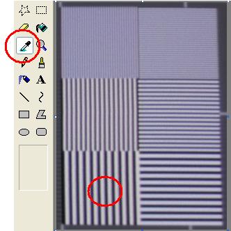
1. Project a resolution pattern like the SMPTE one. There are two boxes at the top with alternating one pixel on/one pixel off lines. The middle boxes are two pixels on/two off, and the bottom pair is three pixels on/three pixels off.
2. Take a picture of the resolution boxes. It will work better if you are close enough to the screen to get just the resolution boxes. You don't want/need the whole screen.
3. Upload the pic to your PC and open with Windows Paint (probably other viewers will work).
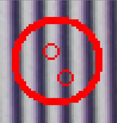
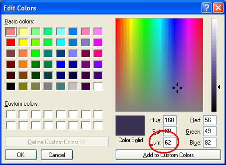
4. Use the eyedropper cursor to pick the darkest part of the "black" line and go to the colors menu\edit colors\define custom colors to get the LUM value.
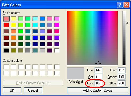
5. Use the eyedropper cursor to pick the brightest part of the "white" line and go to the colors menu\edit colors\define custom colors to get the LUM value.
6. Use the formula: white LUM value - black LUM value / (white LUM value + black LUM value) x 100 = MTF
So in the example: 187 - 62 / (187 + 62) x 100 or 125 / 249 x 100 = 50.2%
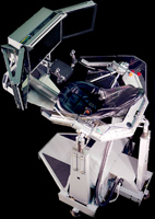
I'm shamelessly using MP's pic of his projector output in the three pixel on/three pixel off section. More accurate readings would be had with a pic of only the resolution bars. *.BMP files probably give better results, too. You need to specify the MTF at 3 pix on/3 pix off @ XXX lumens or whatever conditions you are measuring.
Enjoy,
Scott
| Description: |
|
| Filesize: |
19.57 KB |
| Viewed: |
14078 Time(s) |
|
| Description: |
|
| Filesize: |
11.13 KB |
| Viewed: |
14078 Time(s) |
|
| Description: |
|
| Filesize: |
32.84 KB |
| Viewed: |
14078 Time(s) |
|
| Description: |
|
| Filesize: |
32.32 KB |
| Viewed: |
14078 Time(s) |
|
_________________
"Were we directed from Washington when to sow and when to reap, we would soon want bread."
Thomas Jefferson
|
|
| Back to top |
|
 |
greg_mitch
Joined: 03 May 2006
Posts: 5320
|
| Posted: Wed Aug 25, 2010 1:43 am Post subject: |
|
|
|
Wouldn't camera settings have to be put in manual in order for pre and post mod reading comparisons?
|
|
| Back to top |
|
|
Nashou66

Joined: 12 Jan 2007
Posts: 16171
Location: West Seneca NY
|
|
| Back to top |
|
|
tse
Joined: 03 May 2006
Posts: 1014
Location: Sweatbucket, Fl.
|
| Posted: Wed Aug 25, 2010 1:52 am Post subject: |
|
|
Improvements or decreases will be easy to measure if the same conditions are used when taking the pics. Probably best to limit the ambient light so the dark lines are as dark as possible.
Scott
_________________
"Were we directed from Washington when to sow and when to reap, we would soon want bread."
Thomas Jefferson
|
|
| Back to top |
|
|
zGman
Joined: 22 May 2006
Posts: 599
|
| Posted: Thu Aug 26, 2010 1:44 pm Post subject: |
|
|
Thanks Scott - That is a really helpful idea & explanation.
What pattern do you use to get your output measurement
(ie. 33% @ xxx lumens), windowed 100 IRE or full screen?
G
|
|
| Back to top |
|
|
WanMan

Joined: 19 Mar 2006
Posts: 10270
|
| Posted: Thu Aug 26, 2010 1:53 pm Post subject: |
|
|
Won't a camera's ability to discern low-light lines be important when in the present of high-light lines (pseudo-ANSI characteristics)? For instance, a camera's CCD might be more accurate capturing an all black field due to its unsaturated CCD sensitivity, but as soon as non-black content is added the CCD might become saturated and less sensitive. I would imagine this could affect the MTF calculation.
The analogy is that if you are listening to orchestra music that is loud the softer instruments being played may not be heard because your ears have become saturated with high dB content. Again, this was only meant to be an analogy as I am dumber than dirt. 
I would imagine a useful experiment would be to take a simple sub-$100 point and shoot camera and compare the results to a prosumer DSLR.
_________________
Trust no one. Absolutely no one. Advice of the board.
|
|
| Back to top |
|
|
WanMan
Joined: 19 Mar 2006
Posts: 10270
|
| Posted: Thu Aug 26, 2010 1:56 pm Post subject: |
|
|
Ooo, this brings up my next curiosity ... in an all black field is there MTF-based resolution?
_________________
Trust no one. Absolutely no one. Advice of the board.
|
|
| Back to top |
|
|
tse
Joined: 03 May 2006
Posts: 1014
Location: Sweatbucket, Fl.
|
| Posted: Thu Aug 26, 2010 2:24 pm Post subject: |
|
|
| zGman wrote: | Thanks Scott - That is a really helpful idea & explanation.
What pattern do you use to get your output measurement
(ie. 33% @ xxx lumens), windowed 100 IRE or full screen?
G |
Attached is a small pattern made up of one on/on off, two on/two off, and three on/three off pixels and lines. You have to rename it to *.bmp (can't attach bmp files) and open it in a viewer like Paint that does not change or compress the picture. The one on/one off has to stay single pixel/line. The SMPTE133 pattern that it is copied from has the rest of the picture at 50 IRE.
Scott
| Description: |
|

Download |
| Filename: |
SMPTE_RES-01.c |
| Filesize: |
3.09 KB |
| Downloaded: |
491 Time(s) |
_________________
"Were we directed from Washington when to sow and when to reap, we would soon want bread."
Thomas Jefferson
|
|
| Back to top |
|
|
tse
Joined: 03 May 2006
Posts: 1014
Location: Sweatbucket, Fl.
|
| Posted: Thu Aug 26, 2010 2:29 pm Post subject: |
|
|
| WanMan wrote: | Won't a camera's ability to discern low-light lines be important when in the present of high-light lines (pseudo-ANSI characteristics)? For instance, a camera's CCD might be more accurate capturing an all black field due to its unsaturated CCD sensitivity, but as soon as non-black content is added the CCD might become saturated and less sensitive. I would imagine this could affect the MTF calculation.
The analogy is that if you are listening to orchestra music that is loud the softer instruments being played may not be heard because your ears have become saturated with high dB content. Again, this was only meant to be an analogy as I am dumber than dirt.
I would imagine a useful experiment would be to take a simple sub-$100 point and shoot camera and compare the results to a prosumer DSLR. |
I don't think the picture from a CRT video projector is going to saturate a camera. Best results will be had when your camera pic has the single pixel/single line part of the pattern covering many of the camera pixels, get close. Try to keep the conditions as similar as possible if you are making comparisons.
Scott
_________________
"Were we directed from Washington when to sow and when to reap, we would soon want bread."
Thomas Jefferson
|
|
| Back to top |
|
|
zGman
Joined: 22 May 2006
Posts: 599
|
| Posted: Thu Aug 26, 2010 7:11 pm Post subject: |
|
|
Hi Scott - I think I follow you on using the camera and 'paint' type
program to get the ratio of on vs off in the alternating line patterns,
and I think I understand that vertical line MTF will indicate the bandwidth
response. What I am trying to figure is what you use to determine
the other condition, "at xxx lumens" ? In other words are you using
a lightmeter on the center of the smpte pattern, or switching to a
all white pattern as a reference for total output?
Thanks,
G
|
|
| Back to top |
|
|
perisoft
Joined: 29 Aug 2007
Posts: 2920
Location: Ithaca, NY
|
| Posted: Thu Aug 26, 2010 7:30 pm Post subject: |
|
|
A quick bit of coding, using an automated camera input or very HQ webcam, ought to be able to automate this, and allow on-screen display of focus quality when doing adjustments. Anyone up for it?
Same should go for astig, really. With enough effort you should be able to hook a web cam up, point it zoomed in at your dot, and have the software understand what the flare is doing so it can tell you which @#$@#%$%^#!@#!%@ goddamn @#%@!#% knob to change.
Ahem.
_________________

|
|
| Back to top |
|
|
Nashou66
Joined: 12 Jan 2007
Posts: 16171
Location: West Seneca NY
|
| Posted: Thu Aug 26, 2010 7:37 pm Post subject: |
|
|
| perisoft wrote: | A quick bit of coding, using an automated camera input or very HQ webcam, ought to be able to automate this, and allow on-screen display of focus quality when doing adjustments. Anyone up for it?
Same should go for astig, really. With enough effort you should be able to hook a web cam up, point it zoomed in at your dot, and have the software understand what the flare is doing so it can tell you which @#$@#%$%^#!@#!%@ goddamn @#%@!#% knob to change.
Ahem. |
Scot already did that too but used a scope to show amplitude when in focus according to a video camera's output.
Poor man's Microvision or Focus for the Blind
With a video camera and an oscilloscope one can optimise focus while watching the scope display even if the screen is not visible from the projector or if you are having trouble seeing the screen well from the projector location. In any case you can have the scope right next to the projector and watch it's display up close. Project a one or two pixel on, one or two pixel off pattern and focus the camera on the screen. Maximize the signal amplitude on the scope and you have the best posible focus. I think this is how autofocus on digital cameras works. Largest peak to peak is best focus.


He also uses it for convergence but then you'd have to move camera all over the screen.
Athanasios
_________________
Don't blame your underwear for your crooked ass~ unknown Greek philosopher
"Republicans believe every day is the Fourth of July, but the Democrats believe every day is April 15." --- President Reagan
One Smart Dog!!!
Marquee High Performance Bellows now shipping!!
Marquee Modifications and Performance Enhancement
Marquee C-element and Bellow removal
|
|
| Back to top |
|
|
perisoft
Joined: 29 Aug 2007
Posts: 2920
Location: Ithaca, NY
|
| Posted: Thu Aug 26, 2010 8:33 pm Post subject: |
|
|
| Nashou66 wrote: |
Scot already did that too but used a scope to show amplitude when in focus according to a video camera's output.
Athanasios |
This might be a bit easier for people to use, though - particularly as rather more people have webcams than scopes.
In other news... if you're blind, why do you care about optimising focus? 
Given the chromatic aberration of my glasses, I sometimes wonder why I bother with corner convergence at all, my self. I've also considered doing convergence incorrectly at the edge of the screen so I see correct convergence from my spot on the couch and everyone else has to deal with the CA for a couple of hours, for once... 
_________________
|
|
| Back to top |
|
|
Nashou66
Joined: 12 Jan 2007
Posts: 16171
Location: West Seneca NY
|
| Posted: Thu Aug 26, 2010 8:39 pm Post subject: |
|
|
| perisoft wrote: | | Nashou66 wrote: |
Scot already did that too but used a scope to show amplitude when in focus according to a video camera's output.
Athanasios |
This might be a bit easier for people to use, though - particularly as rather more people have webcams than scopes.
In other news... if you're blind, why do you care about optimising focus?
Given the chromatic aberration of my glasses, I sometimes wonder why I bother with corner convergence at all, my self. I've also considered doing convergence incorrectly at the edge of the screen so I see correct convergence from my spot on the couch and everyone else has to deal with the CA for a couple of hours, for once... |
LOL Good one!!

Nashou
_________________
Don't blame your underwear for your crooked ass~ unknown Greek philosopher
"Republicans believe every day is the Fourth of July, but the Democrats believe every day is April 15." --- President Reagan
One Smart Dog!!!
Marquee High Performance Bellows now shipping!!
Marquee Modifications and Performance Enhancement
Marquee C-element and Bellow removal
|
|
| Back to top |
|
|
tse
Joined: 03 May 2006
Posts: 1014
Location: Sweatbucket, Fl.
|
| Posted: Fri Aug 27, 2010 12:50 am Post subject: |
|
|
| perisoft wrote: | A quick bit of coding, using an automated camera input or very HQ webcam, ought to be able to automate this, and allow on-screen display of focus quality when doing adjustments. Anyone up for it?
Same should go for astig, really. With enough effort you should be able to hook a web cam up, point it zoomed in at your dot, and have the software understand what the flare is doing so it can tell you which @#$@#%$%^#!@#!%@ goddamn @#%@!#% knob to change.
Ahem. |
Yes, that would be good. Combine the camera reading from all the columns (when looking at vertical alternating black and white lines) of pixels into relative light intensity. When interested in the horizontal lines take the reading from the camera rows of pixels.
It is amazing how tight the focus can be made when looking at a real time display of the light levels of the black and white lines from a one on/one off pixel or line test pattern. Just adjust for largest difference between the light and dark lines.
Adjusting the stigs for round dots needs regular camera scan display zoomed in.
Scott
_________________
"Were we directed from Washington when to sow and when to reap, we would soon want bread."
Thomas Jefferson
|
|
| Back to top |
|
|
tse
Joined: 03 May 2006
Posts: 1014
Location: Sweatbucket, Fl.
|
| Posted: Fri Aug 27, 2010 12:57 am Post subject: |
|
|
| zGman wrote: | Hi Scott - I think I follow you on using the camera and 'paint' type
program to get the ratio of on vs off in the alternating line patterns,
and I think I understand that vertical line MTF will indicate the bandwidth
response. What I am trying to figure is what you use to determine
the other condition, "at xxx lumens" ? In other words are you using
a lightmeter on the center of the smpte pattern, or switching to a
all white pattern as a reference for total output?
Thanks,
G |
Use a 10 or 20% (area) white square (at 100 IRE) in a black background and measure lux and multiply times square meters for a lumen reading or use a screen with gain of one and measure foot lamberts and multiply times square feet for lumens. Change pattern to alternating lines and take the pic for measuring MTF. Close up, perfectly focused pic will give best readings.
Scott
_________________
"Were we directed from Washington when to sow and when to reap, we would soon want bread."
Thomas Jefferson
|
|
| Back to top |
|
|
zGman
Joined: 22 May 2006
Posts: 599
|
| Posted: Fri Aug 27, 2010 2:44 am Post subject: |
|
|
Thanks for catching my question - So with a repeatable test
setup, in theory perhaps one could get a plot of MTF vs. output vs.
contrast (drive level? beam current?) for different tube types,
focus coils, VNB mods etc?
G
|
|
| Back to top |
|
|
tse
Joined: 03 May 2006
Posts: 1014
Location: Sweatbucket, Fl.
|
| Posted: Fri Aug 27, 2010 2:51 am Post subject: |
|
|
You betcha. Put a repeatable number on the measurement instead of "well, I think it is better" eyeball measurements.
Scott
_________________
"Were we directed from Washington when to sow and when to reap, we would soon want bread."
Thomas Jefferson
|
|
| Back to top |
|
|
Spanky Ham

Joined: 22 Mar 2006
Posts: 5643
Location: Comedy Central
|
|
| Back to top |
|
|
WanMan
Joined: 19 Mar 2006
Posts: 10270
|
| Posted: Sat Aug 28, 2010 7:13 pm Post subject: |
|
|
The interesting thing about them comparing the RS20 (which I bought recently) is that I have always known that DLP was a heck of a lot sharper than LCoS, but that the followers of LCoS (including me) liked this lack of ultra-sharpness as it helped to merge the pixel edges and afford a more analog presentation (or a less digital one, take your pick).
As such, the whole comparison of sharpness seems to be for the unwashed masses that couldn't realize the obvious from the very first observation opportunity. But what is really surprising as this shows how two DLP projectors can be drastically different in sharpness. Caveat should also include the difference in lens assy might play into this.
_________________
Trust no one. Absolutely no one. Advice of the board.
|
|
| Back to top |
|
|
|
|


