| Author |
Message |
gjaky
Joined: 05 Jun 2010
Posts: 2802
Location: Budapest, Hungary
|
| Posted: Tue Jun 15, 2010 5:47 pm Post subject: 9PG xtra H deflection dying and dying and... |
|
|
I own a NEC 9PG xtra for 3-4 months. It has less than 1000 working hrs. The PJ is still in setup/test state. 3 weeks ago I wanted to turn off via PC, but it not responded to the order (but it projected the picture) after several seconds it turned off but with error message (HV failed). Next I couldn't turn on, and the H-fail led lit. The H-out transistor was shorted. I didn't think it is serious so I bought a new transistor, and put in. At least I checked the area of the transistor for more shorts, but nothing. With the new transistor it turned on, and has picture (from video in) I ran it about 0.5-1 hour, and worked fine, it is alived the turn off too. After that the PJ have rested for a week, then I wanted to do some more adjustments on it. Turning on: ok. There was set to video in, but I wanted to use the RGB so I switched to my preset (via PC again) but there was no picture just the OSD message with preset name and the source name. After several seconds the PJ again sut down with error messages (video board not responding, H fail) Sooo I had again a shorted H-out transistor.
I already have a service manual.. I have checked almost every caps on H-deflection area (beyond 10uf, and the high voltage foil caps too) everything seemed ok. I have a new transistor but I don't have the courage to put it in.
The question is: what is going on?
|
|
| Back to top |
|
 |
jarseneau
Joined: 06 Nov 2007
Posts: 323
Location: WI
|
| Posted: Thu Jun 17, 2010 1:39 am Post subject: |
|
|
This should be useful from the NEC 6/9PG manual. I'm not sure if it matters what kind of input is active at the time but I was told to feed it composite video during these adjustments. I would also check them when feeding the highest resolution signal you plan to use. ie 720p
4) Horizontal Amplitude Adjustment
4)-1 Connect a horizontal deflection yoke to the HR, HG, and HB connectors.
4)-2 Adjust VR5005 H-WIDTH to 1.8±0.1 V at voltage of PA pin 2.
4)-3 Adjust VR5301 F/V so that the voltage becomes 3.00±0.02V at TP5303 when the horizontal sync signal
frequency is 30kHz.
Note: Be sure to make adjustment after checking to be sure that the horizontal sync frequency at
TP5305 is 30.00±0.01 kHz.
4)-4 Check to be sure that when the power at pin 1 of PA is removed, D5023 lights and that pin 1 of LP
becomes in excess of 10V.
4)-5 When the HG connector is removed and the power of 4)-.2 is conncected to pin 1 of PA, check to make
sure that D5023 remains lit.
4)-6 Remove the power at pin 1 of PA once again and connect the HG connector for connection off and that
pin 1 of LP drops below 1V.
5) VR5002 H-POSITION Adjiustment
5)-1 Make sure that pin 2 of HV and pin 1 of DP show the waveform of Fig. 2)-7.
5)-2 Check to be sure that VR5002 is set in the mechanical center.
5)-3 Make sure that the waveform of Fig. 2)-7 moves back and forth with respect to the horizontal sync signal
when the voltage at pin 8 of DP is changed from 0 to 12V.
6) Horizontal Deflection Output Transistor Protective Circuit Adjustment
Connect a digital voltmeter to TP5007 (+ terminal) and TP5006 (- terminal), apply a 1S-kHz si'gnal input, and
adjust VR5004 H-OUT PROTECTOR to 2.0 ± 0.1 V.
Sorry if some of the text is confusing. It is from the NEC manual after all  but some of the mistypes could be due to the cut and paste from the .pdf file. but some of the mistypes could be due to the cut and paste from the .pdf file.
_________________
Jerry
|
|
| Back to top |
|
|
gjaky
Joined: 05 Jun 2010
Posts: 2802
Location: Budapest, Hungary
|
| Posted: Sat Jun 19, 2010 4:07 pm Post subject: |
|
|
It is getting more exciting... I get a tip about the pc control software is not very reliable, and maybe that is killing the deflection. So I focused on to control the PJ without the software (I don't have RC)
Three days ago I put in the new transistor, it is powered up well and has picture from video in. It ran a couple hours without any issue. I performed the adjustment of the deflection transistor protective circuit (before adjusting the difference from the ideal value was 0.5V) Today I decided to go forward in testing, and connected to RGB. I started from the ground 640X480@60Hz, went well, so I moved on to 800X600 at that resolution had some problem -it couldn't synchronize the picture well, but I went on a higher resolution to see what is happening. At 1024X768 again have a good picture. The next resolution was 1152X864 -with no problem. But in 1280X1024 died again  had similar picture as in 800X600; the (high frequency) sound of the deflection varied hardly, and after 2-3 sec the PJ shut down with the "usual" error code (FC) had similar picture as in 800X600; the (high frequency) sound of the deflection varied hardly, and after 2-3 sec the PJ shut down with the "usual" error code (FC)
Any idea, maybe?
|
|
| Back to top |
|
|
gjaky
Joined: 05 Jun 2010
Posts: 2802
Location: Budapest, Hungary
|
|
| Back to top |
|
|
Mark_A_W
Joined: 15 Mar 2006
Posts: 3068
Location: Sunny Melbourne Australia
|
| Posted: Wed Jun 23, 2010 6:06 am Post subject: |
|
|
It has to be the EXACT original transistor.
Doug Baisey tried to find a substitute, and all the replacements, which were "better" on paper, failed in a short amount of time (weeks at most).
We do not know of a working substitute.
|
|
| Back to top |
|
|
gjaky
Joined: 05 Jun 2010
Posts: 2802
Location: Budapest, Hungary
|
| Posted: Tue Jul 06, 2010 5:01 pm Post subject: |
|
|
Hardly I found an original H-out transistor, but something is still wrong. The new transistor getting too hot very fast. The adjustments are in mid-like position.
It worked for about 2 minutes in video mode, and turned off with a lighting H-fail LED... I thought it is the end again. Shortly after I tried to turn on again the machine, to see if the new transistor is dead. And it is NOT! It turned on, and had picture again, so I quickly turned off before something new happening. So I get the board out to find something.
I found a very-very confusing aberration from the service manual's schematic. On Q5215 place it signs a 2SC2751 transistor, but in my board there is a toshiba 2SK1544, which is a MOSFET  -and it has an additional resistor (470R) between it's gate and source. I know mosfets acts nearly as bjt's in some cases, but here the transistor is in a quasi complementer power amplifier circuit. It has to be symmetric, but in this case I don't think so... -and it has an additional resistor (470R) between it's gate and source. I know mosfets acts nearly as bjt's in some cases, but here the transistor is in a quasi complementer power amplifier circuit. It has to be symmetric, but in this case I don't think so...
I know there are some revisions of the def board. This is a known modification, or just a strange/stupid replacement? Should I left in this way (it worked more or less) or follow strictly the schematic?
It seems the board is very moody, any more tips what to measure?
|
|
| Back to top |
|
|
gjaky
Joined: 05 Jun 2010
Posts: 2802
Location: Budapest, Hungary
|
| Posted: Thu Jul 08, 2010 7:56 am Post subject: |
|
|
Ok... let's simplify the question...
Does anybody have the same view when looking at a PG9200 deflection board?
|
|
| Back to top |
|
|
Curt Palme
CRT Tech
Joined: 08 Mar 2006
Posts: 24396
Location: Langley, BC
TV/Projector: All of them!
|
| Posted: Thu Jul 08, 2010 3:28 pm Post subject: |
|
|
the problem with all PG sets now (less with the Xtra as they are newer) are that all the parts are now aging. it used to be that the H output transistor would blow only due to failure of the transistor, but now I'm seeing other components fail which then causes the H output to fail. I've thrown out several defection boards due to blowing 5+ output transistors, without being able to find out what the cause of the problem was, and everything else around the transistor seems OK.
also, beware that there are some 'counterfeit' HOT transistors out there, that are substandard and will run hot and fail. I had a local supplier give me 10 of those before I tried a different source, which worked fine.
|
|
| Back to top |
|
|
gjaky
Joined: 05 Jun 2010
Posts: 2802
Location: Budapest, Hungary
|
| Posted: Fri Sep 17, 2010 2:58 pm Post subject: |
|
|
I bought a working PG6 xtra to compare the deflection boards. Finally now it seems the board is working well (up to 1280x1024) The 9200's deflection board is in the 6200's chassis now.
Only one creepy idea remained: Can the system board kill the deflection board? -I suspect the answer is yes, BUT in this case the board was killed always in a certain resolution (1280x1024). It is possible?
(How) Can I prove this without killing the deflection board?
|
|
| Back to top |
|
|
CasetheCorvetteman

Joined: 09 Nov 2008
Posts: 6326
Location: Australia
|
| Posted: Fri Sep 17, 2010 9:33 pm Post subject: |
|
|
|
Pull that system board and see if those capacitors have eaten it away yet!! Pull your point board and check that while youre at it, there is some capacitors on there that will kill that one as well.
|
|
| Back to top |
|
|
hansilili

Joined: 09 Mar 2007
Posts: 302
Location: Köln, Germany
|
| Posted: Sat Jan 15, 2011 12:21 pm Post subject: |
|
|
I accidently screwed up the setting of the F/V pot and maybe also the H output. Now the picture is slightly instable.Think I need to get an oszilloscope and readjust.
Can someone send me the service manual for the 6pgxtra please?
Will a Deflection board with original factory settings from my spare machine work or would this one need individual adjustment of the pots too?
Thanks an best regards
HAns
_________________
HansA, alles andere ist euer Bier!
|
|
| Back to top |
|
|
gjaky
Joined: 05 Jun 2010
Posts: 2802
Location: Budapest, Hungary
|
| Posted: Sat Jan 15, 2011 12:58 pm Post subject: |
|
|
F/V means Frequency to voltage, there are measure points (now I don't know exactly which they are) where the voltage must be equal to the scanning frequency (if 57kHz the Fh then the voltage must be 5,7V and so on)
H out is literally the adjustment of the H out transistor protection. If I remember well the TP(5)006 and TP(5)007 are the measure points of this. And should be measured to 2V when a 15kHz signal applied to the input, however on my both set was slightly lower (~1,6-1,8V) by default.
Generally You can use the spare deflection board, but some minor issues can occur.
|
|
| Back to top |
|
|
kschmit2
Joined: 09 Mar 2006
Posts: 1141
Location: Heidelberg, Germany
|
| Posted: Sat Jan 15, 2011 1:01 pm Post subject: |
|
|
|
Hans, PM sent
|
|
| Back to top |
|
|
kschmit2
Joined: 09 Mar 2006
Posts: 1141
Location: Heidelberg, Germany
|
| Posted: Sat Jan 15, 2011 1:09 pm Post subject: |
|
|
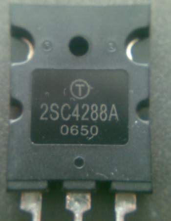
gjaky, I do have a spare Deflection board from a 9PG. It has a Toshiba 2SC4288A on it.
The board came out of a very low hour 9PG that I test-ran at 1280x1024 at 60 Hz for 100 hours.
Kai
|
|
| Back to top |
|
|
gjaky
Joined: 05 Jun 2010
Posts: 2802
Location: Budapest, Hungary
|
| Posted: Sat Jan 15, 2011 1:20 pm Post subject: |
|
|
kschmit2: Oh thanks, but I think my problem is depper then this because I obtained a place where I can get original 2SC4288A-s but one already gone after ~4 hours of working, Now I replaced a bounch of capacitors on the board but now it works worse then ever, because a strange noise appeared on the green (only on green) when sharp vertical lines on the picture.... Maybe the UPC ic is the main problem.
Now I thinking on turning a whole working plain PG def board (which to I have acces "for free") to a xtra def board...
|
|
| Back to top |
|
|
kschmit2
Joined: 09 Mar 2006
Posts: 1141
Location: Heidelberg, Germany
|
| Posted: Sat Jan 15, 2011 1:27 pm Post subject: |
|
|
|
do you need the service manual as well?
|
|
| Back to top |
|
|
gjaky
Joined: 05 Jun 2010
Posts: 2802
Location: Budapest, Hungary
|
| Posted: Sat Jan 15, 2011 1:31 pm Post subject: |
|
|
|
No thanks! I have that, but even with that it's a hard nut... :/
|
|
| Back to top |
|
|
Curt Palme
CRT Tech
Joined: 08 Mar 2006
Posts: 24396
Location: Langley, BC
TV/Projector: All of them!
|
| Posted: Sat Jan 15, 2011 4:02 pm Post subject: |
|
|
|
There are a bunch of counterfeit 2sc4288 transistors out there, I bought 6 locally that lasted 20 minutes and died. Bought some from somewhere else, and they were fine. No other changes done to the deflection board other than putting in a proper transistor, not a Chinese made one.
|
|
| Back to top |
|
|
the_maniac
Joined: 10 Jul 2009
Posts: 111
Location: Austria - Europe
|
| Posted: Sun Jan 23, 2011 11:10 pm Post subject: |
|
|
hello,
i bought one 6PG+ for 10 today  which has HFail. which has HFail.
is there any source where i can get an original 2SC4288A ?
_________________
www.diy-community.de
|
|
| Back to top |
|
|
gjaky
Joined: 05 Jun 2010
Posts: 2802
Location: Budapest, Hungary
|
| Posted: Mon Jan 24, 2011 7:16 am Post subject: |
|
|
Hi!
PM Kschmit2!
But look around for leaky caps on the board as well
|
|
| Back to top |
|
|
|
|